CNC Lathe / Sliding Headstock Lathe Automation Cell
For CNC lathe and sliding headstock lathe users, we provide stand-alone automatic loading and unloading units covering bar stock/coil stock loading, bar feeding, turning, cut-off and part removal, part discharge, inline inspection and OK/NG sorting, configured to the workpiece specification and cycle time.
Solution Overview
For CNC lathe and sliding headstock lathe users, a standalone automatic loading and unloading cell
The CNC lathe / sliding headstock lathe automation cell is a loading and unloading solution for single machines, covering 7 steps: "bar/disk material loading — bar feeding/loading — turning — cut-off and part retrieval — discharge — in-line inspection — OK/NG sorting". Loading and unloading for sliding headstock lathes and lathes each have their own characteristics: slender parts on a sliding headstock lathe need dedicated loading and receiving mechanisms to avoid bending deformation, while disk-type parts on a lathe are fed from a material bin or vibratory bowl, with a robot retrieving the part and feeding it into the spindle. The feeding mechanism supports automatic bar/disk material loading and vibratory bowl or material bin feeding, with material shortage detection and alarm.
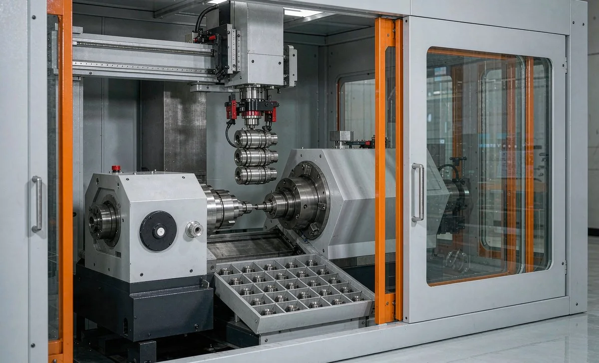
For companies that use CNC lathes and sliding headstock lathes for precision part machining, we provide standalone automatic loading and unloading cells.
The complete process is: Bar/coil stock loading → Material feed/loading → Turning → Cut-off and part removal → Discharge → Inline inspection → OK/NG sorting; configure the feeding mode and fixtures according to workpiece specifications, material and machining cycle time.
Solution configuration
Four Modules Combined by Workpiece and Cycle Time, Available as Options
Feeding Mechanism
- Automatic bar/coil stock loading
- Vibratory bowl or material bin feeding
- Configured by workpiece specification
- Material shortage detection and alarm
Picking and Loading
- Vision positioning or mechanical positioning
- Robot / manipulator part pick-up
- Flexible fixture adapts to multiple specifications
- Material feed interlocked with loading
Discharge and Transfer
- Automatic part removal after cut-off
- Discharge into bins or onto the line
- Can Integrate with Downstream Process Steps
- Full-bin detection and bin changeover
Inspection and Sorting
- In-line dimension / appearance inspection
- Automatic OK/NG Judgement
- Good part / defective part separation
- Inspection data can be sent back
process Workflow
From loading to sorting, one standalone machine unit does it all
- 01 Bar Stock / Coil Stock Loading
- 02 Material Feed / Loading
- 03 Turning
- 04 Cut-Off and Part Removal
- 05 Discharge
- 06 In-Line Inspection
- 07 OK/NG Sorting
Critical Stages
Loading and Unloading for Sliding Headstock Lathes and Lathes Have Their Own Characteristics, Corresponding Respectively To
Loading and Unloading of Slender Parts for Sliding Headstock Lathes
Slender shaft parts machined on a sliding headstock lathe require dedicated loading and receiving mechanisms to prevent bending and deformation, working with automatic bar feeding for continuous machining.
- Dedicated loading and receiving mechanism for slender parts
- Automatic material feeding interlocked with cutting and pick-up
- Prevents bending and deformation of slender parts
- Can integrate with part discharge and inline inspection
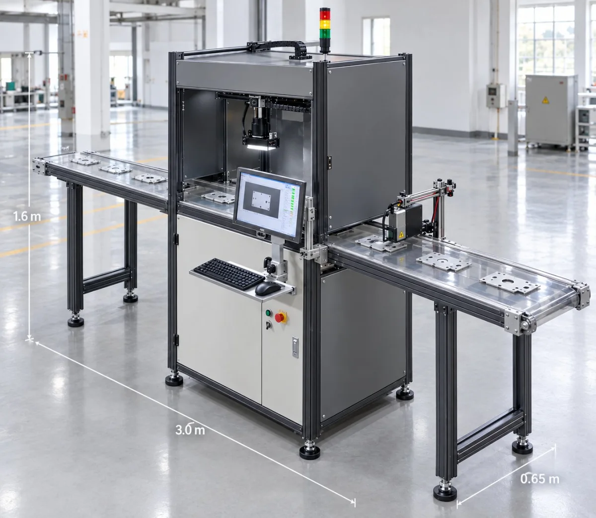
Lathe Disc-Type Part Loading and Unloading
Disc-type parts machined on lathes are fed from a material bin or vibratory bowl feeder; the robot picks the part and loads it into the spindle, and after machining automatically removes and discharges it.
- Material bin or vibratory bowl feeding
- Robot picks the part and feeds it into the spindle
- Automatic part removal and discharge after machining
- Can integrate with inline inspection and sorting
Applicable workpiece
Handles multiple specifications, small-to-medium batches and large-volume production
- Primarily sliding headstock lathe machining
- Dedicated loading and unloading for slender parts
- Part discharge after cut-off
- Dimension and coaxiality inspection
- Mainly Lathe Machining
- Material bin feeding for disc-type parts
- Inner hole and outer diameter inspection
- Medium-Volume Production Line
- Lathe or sliding headstock lathe machining
- Vibratory bowl or material bin feeding
- Thread and sealing surface inspection
- High-volume production line
- Sliding headstock lathe machining
- Continuous feeding and cut-off
- Dimension and appearance inspection
- High-volume production line
Delivery and After-sales
Follow-through from requirement confirmation to trial production acceptance
- 01 Requirement confirmation and site survey
- 02 Solution design and simulation
- 03 Equipment manufacturing and procurement
- 04 Integration, installation and commissioning
- 05 Trial production and process optimization
- 06 Acceptance and Delivery
- 07 After-sales service and follow-up visits
Remote technical support and regular follow-up visits are provided after delivery; repairs for non-human-caused damage are free of charge within the warranty period, and paid maintenance and upgrade services are provided after the warranty expires.
Common Question
Common questions about CNC lathe / sliding headstock lathe automation cells
Do sliding headstock lathes and lathes use the same loading and unloading mechanism?
No. The solution addresses the two correspond respectively to: slender shaft parts machined on a sliding headstock lathe require dedicated loading and receiving mechanisms to avoid bending and deformation, combined with automatic bar feeding for continuous machining; disc-type parts turned on a lathe are fed from a material bin or vibratory feeder, with the robot picking up the part and loading it into the spindle, then automatically removing and discharging it after machining.
Which Workpieces Does It Cover?
3 typical workpiece types: Precision Shafts (motor shafts / drive shafts / stepped shafts), Sleeves (bearing sleeve / bushing / guide sleeve), Connectors (hydraulic fittings / pneumatic fittings / quick couplings), and can also cover hardware parts (nuts / valve cores / small structural parts).
What types of feeding mechanisms are available?
Automatic loading of bar stock / coiled stock, fed by a vibratory bowl or material bin, configured to the workpiece specification, with material shortage detection and alarm. The picking end can use vision positioning or mechanical positioning, with flexible grippers to suit multiple specifications, and material feeding is interlocked with loading.
How are discharge and inspection combined?
Automatic part removal after cutting, discharging into a frame or onto the line, able to connect to the next process step, with full-frame detection and frame changeover. The inspection and sorting stage provides inline dimensional / appearance inspection, automatic OK/NG judgement, and separation of good parts from defective parts, with inspection data sent back.
What determines the configuration?
Based on 4 configuration dimensions: workpiece specification, material, cycle time and batch size. The solution is a combination of four modules — feeding mechanism, pick-and-load, discharge and transfer, inspection and sorting — which can be selected as needed.
Submit Samples and Requirements
Send us the workpiece drawing, machining equipment, current cycle time and site conditions, and our solution engineers will recommend the material bin type, picking method and inspection configuration.
Submitted successfully
We have received your sample testing request. A solution engineer will contact you within 1 business day via contact you.
Need to assess imaging conditions, defect criteria and cycle time item by item? Go to the Full Requirement Assessment →
Configured to Your Workpieces and Cycle Time
Send us the workpiece drawing, machine tool equipment and production cycle time, and our solution engineers will recommend the corresponding material bin type, picking method and inspection configuration.