PCB Component Presence/Absence Inspection
Judges whether components on a PCB are mounted, correctly positioned and correctly polarized, for inline verification after SMT and at through-hole insertion process steps.
inspection Overview
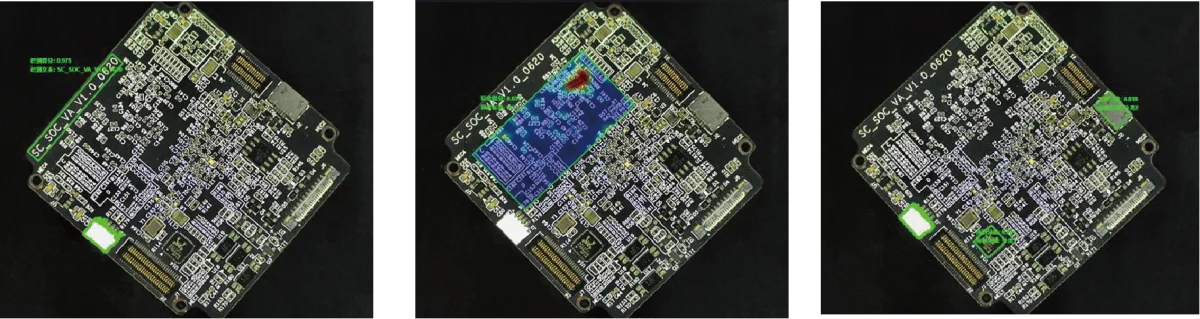
PCB component presence/absence inspection: determines whether components on the PCB are mounted, whether their position is offset, and whether polarity is correct, suitable for inline verification after SMT and at the through-hole insertion process step. Judgement usually does not assess details such as threads or dimensions, but rather Whether the visual feature at that position exists and matches expectations, output OK / NG and interlock with the production line.
Judges whether components on the PCB are placed, whether positions are offset and whether polarity is correct; suitable for inline verification after SMT and at the insertion process step.
The feasibility of "PCB component presence/absence inspection" depends on Whether the visual features of the object are stable and distinguishable, as well as the on-site optical and tooling conditions. Each item is expanded below in the order commonly used in inspection engineering.
Object Characteristics
How the object appears in the image
- Component sizes vary widely, from 0201 to large connectors
- Hundreds of components on one board must be verified position by position
- Polarized components (capacitors, diodes, ICs) fail if installed in reverse
- The board surface has many background features such as silkscreen, pads and traces
inspection Challenges
Where Problems Really Occur on Site
- Small components cannot be resolved at low resolution
- Dense component areas interfere with each other
- Pads and components are the same color (e.g., tin-plated pads and silver components)
- Polarity marks are subtle and easily confused with silkscreen
Vision Judgement method
How acceptance criteria are set and why
The basic criterion is Check each position for component presence, inspection areas are usually created from component positions (which can be generated from CAD data).
Polarity judgement requires recognizing the correspondence between markings on the component body (color band, notch, dot) and the silkscreen, which demands higher resolution.
Applicable algorithm
Choose by the Form of the Acceptance Criteria, Not by Complexity
Multi-region verification
Judge component presence/absence and offset position by position against the designators
Classification / Mark Recognition
Identify component type and polarity marking
Optical Precautions
Imaging conditions set the upper limit of feasibility
- Common PCB inspections Coaxial light or ring light, ensuring even illumination of components and silkscreen
- Metal pads are highly reflective; use diffuse or polarized light to reduce specular reflection
- Small component inspection requires high resolution and a low-distortion lens
OK / NG Output
How results are judged and passed to the production line
| Inspection Status | judgement | Interlocking Action |
|---|---|---|
| All components present, position and polarity correct | OK | release |
| Missing component present | NG | Block as a missing label |
| Position offset or polarity error | NG | Treat as a defect |
Applicable Industry
This type of inspection is common in the following industries
Common Question
The most common questions about this object
A single board carries hundreds of components - can all of them be inspected?
Yes, but it usually requires multiple cameras or multiple shots to cover the area in zones for position-by-position verification. Component density and the required resolution together determine how many views are needed.
How is component polarity determined?
It relies on the correspondence between the polarity mark on the component body (color band, notch, dot) and the silkscreen on the board. The mark is usually very small and demands high resolution; it is recommended to provide actual samples to validate readability.
What is the difference from AOI equipment?
AOI normally targets dedicated inspection of solder joints and placement quality and has a comprehensive acceptance criteria system; the visual inspection in this solution focuses more on presence judgements such as "presence/absence, position, and polarity". The two are complementary, and the choice depends on which acceptance criteria need to be covered.
What are the acceptance criteria for this object?
The basic acceptance criteria: judge whether each component is present, position by position. Inspection areas are usually established by component position (they can be generated from CAD data).
What are the illumination requirements for this type of object?
PCB inspection commonly uses coaxial or ring light to ensure uniform illumination of components and silkscreen. Metal pads are highly reflective, so diffuse light or polarization is recommended to reduce specular reflection.
What Are the Inspection Accuracy and Minimum Detectable Size?
It depends on the combination of field of view and camera resolution, and is affected by the lens, illumination and algorithm. To be added — the configuration must be derived from your minimum defect size, subject to the results of a measured sample trial.
How Do We Verify That Our Product Can Be Detected?
Please provide good PCBs and sample boards with known missing placement, offset and polarity errors, and state the minimum component size.
Submit sample testing
Please provide good PCBs and sample boards with known missing placement, offset and polarity errors, and state the minimum component size.
Submitted successfully
We have received your sample testing request. A solution engineer will contact you within 1 business day via contact you.
Need to assess imaging conditions, defect criteria and cycle time item by item? Go to the Full Requirement Assessment →
Send Us Your Workpiece and We Will Show You the Measured Results
Provide several OK and NG samples, and the solution engineer will run actual imaging and judgement tests on the equipment, then give inspection configuration recommendations that can be implemented, rather than just reading a specification table.