Cut-Panel Inspection for Garment and Technical Textile
How cut panels are inspected in garment and technical textile production: pattern tolerance, notch and hole position, ply alignment and surface defects.
This Category positioning
For in-line appearance and contour inspection of fabric, leather, non-woven fabric and composite material cut pieces and web/sheet material
The visual inspection solution for cut-piece inspection addresses cut pieces cut from flexible materials (as well as roll materials, sheet materials, and die-cut parts). It inspects surface defects on cut pieces such as stains, color differences, damage, holes, scratches, fuzz and yarn breakage, and foreign matter, as well as whether the cut-piece contour, hole positions, and notches are within tolerance. It is usually installed on a tension-controlled material feed mechanism, with line-scan or area-scan cameras and dedicated illumination, and outputs OK/NG results mapped to cut-piece positions; it can be interlocked with cutting machines, stitching stations, or sorting mechanisms.
The difficulty in cut-piece inspection is not "can it be captured clearly", but The irregularity of flexible materials themselves: fabric has weave texture and prints, leather has natural grain, non-woven fabric has randomly distributed fibers, and foam has a cellular texture — these normal textures all look like defects in the image, and suitable illumination must be used to separate them from real defects.
Because material forms differ, the way material is fed and imaged also differs: cut piece Mostly single-sheet or stacked loading, suitable for area-scan cameras with a sheet separation mechanism; Roll material For continuous feeding, line-scan cameras are preferred to obtain equal-interval imaging; Sheet material lies in between; Die-cut Parts Small in size and large in quantity, they are usually paired with automatic loading and sorting.
Standard output for this solution category OK / NG and Defect Position. For cut-piece products, position information is especially important — because it determines whether the piece must be scrapped entirely or can be nested so as to avoid the defect, which directly affects material utilization.
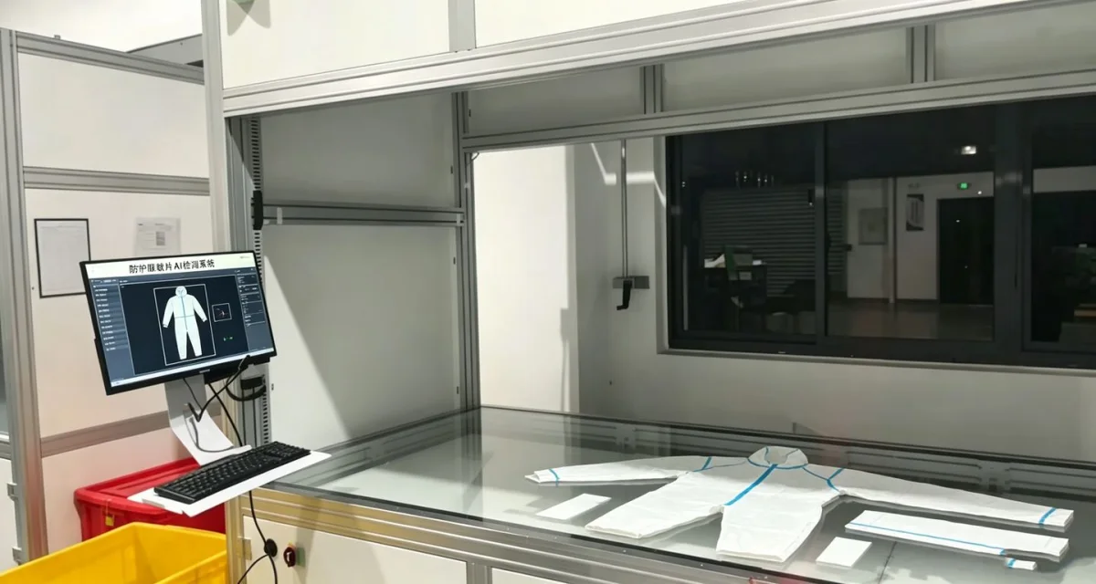
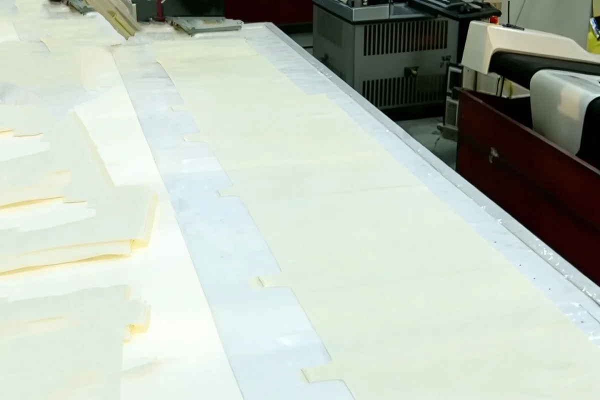
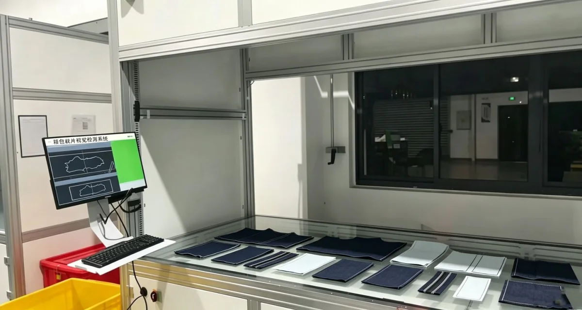
This Category Solution
Existing Solution Pages and Reserved Solution Slots
This type of solution is subdivided by inspection object and material. The table below lists the solution pages already built; the remaining sub-solution slots are reserved and will go live once the materials are complete.
inspection Scope
What is typically inspected for these problems
| inspection item | Judgement Item | Typical Output |
|---|---|---|
| Surface Defect | Stain, color difference, damage, hole, scratch, fuzz and yarn breakage, foreign matter | Defect type + coordinates |
| Contour and Dimensions | Whether the cut-piece contour, hole positions and notches are within tolerance | Dimension Deviation |
| Cut Piece Orientation | Front/back, left and right hand pieces, straight and bias direction | Orientation Judgement |
| Splicing and Alignment | Splice position, plaid / stripe alignment | Alignment Deviation |
| Stacking and Sheet Separation | Whether multi-layer cut pieces are separated correctly and free of sticking | Sheet separation failure flag |
| Marking and Traceability | Presence and legibility of cut-piece numbers and batch markings | Code value |
inspection Object
Common inspection objects and materials
Typical defect
Defects These Solutions Mainly Target
| Defect Types | Typical Manifestations | Inspection Focus Points |
|---|---|---|
| Stains and Oil Stains | Local gray level / hue inconsistent with the surroundings | Distinguishing from the material's natural texture requires diffuse light |
| color difference | Chromaticity deviation between cut pieces in the same batch or within one piece | Requires a stable light source and white balance reference to define reasonable color difference |
| Damage and Holes | Missing material, holes, tears | Transmitted light gives the highest contrast |
| scratch | Linear surface damage | Low-angle light or stripe light reveals it most clearly |
| Fuzz and Yarn Breakage | Fiber breakage, exposed fly fibers | Distinguishing these from normal pile / weave is the main source of false calls |
| foreign matter | Trapped hair, fiber clumps and particles | Low contrast with foreign matter of the same color family, requiring multispectral or dedicated illumination |
| Wrinkles and Indentations | Deformation caused by material feed or stacking | Use striped light or photometric stereo to judge shape anomalies |
| Contour and out-of-tolerance dimensions | Cut-piece contour or hole position does not match the drawing | Measure after calibration; account for the effect of stretching during feeding |
Technology Architecture
First solve "can it be seen", then "can it be judged accurately", and only then automatic rejection and data records
The implementation sequence for cut-piece inspection is fixed: Imaging sets the upper limit, the algorithm sets the lower limit, software determines whether it can be used long term, and automation determines whether labor can be saved. If any one of the four layers does not hold, the project does not hold — the first layer almost determines the project's ceiling, and the remaining three can only work within the information the previous layer provides. If a defect cannot be distinguished at all in the image, no algorithm, however strong, can recover it.
Layer 1 · Visual Imaging
First solve the "can it be seen" problem
- 2D area-scan vision: single / stacked cut pieces, hole position and contour
- 2D line-scan vision: continuous roll material, long-format cut pieces
- Multiple cameras / multi-angle vision: area stitching for large cut pieces
- 2.5D surface topography: wrinkle, indentation, lifting and other topography anomalies
- 3D vision: height, dents, warpage, flatness
- Special optical imaging: low angle, coaxial, transmitted, multispectral
Layer 2 · Vision Algorithm
Choose the algorithm by defect nature; do not apply AI across the board
- Traditional vision: dimensions, contour, position, presence/absence, hole position, gray level, area, length, width
- AI vision: appearance defects, complex textures, scratches, stains, foreign matter, material anomalies and complex-form defects
- 3D algorithms: height, pits, protrusions, warpage, flatness, surface topography
- AI task types: classification / object detection / segmentation / anomaly detection
Layer 3 · Vision Software
Organize different algorithms into one maintainable inspection process
- Product recipe management, inspection parameter management
- Camera management, light source control, algorithm flow management, AI model invocation
- OK/NG judgement, defect classification, image saving
- Data logging, report statistics, historical queries, user permissions
- PLC communication, data interface, product traceability
Fourth Layer · Automation Control
Inspection results must ultimately act on the production line
- Loading → Positioning → Visual Inspection → NG Rejection → OK Unloading → Data Logging
- Can integrate conveying mechanisms, loading and unloading mechanisms, manipulators and positioning fixtures
- Can integrate sorting mechanisms, PLC, MES / production data systems
- The rejection method is determined by the on-site equipment structure: air blow-off, flap, robot pick-out or marking
Software Closed Loop
- 01 image acquisition
- 02 Algorithm analysis
- 03 AI recognition
- 04 Combined Judgement
- 05 Data Recording
inspection Method
Combined Route of Imaging, Algorithm and Judgement
Material Travel and Imaging
Material form determines the camera type
- Continuous roll material travel: line-scan camera + equally spaced triggering
- Single / stacked cut pieces: area-scan camera + piece separation and positioning
- Sheets: area-scan or line-scan, chosen by area and cycle time
Tension and Web Guiding
The number-one engineering problem with flexible materials
- Tension fluctuation distorts the dimensional measurement of cut pieces
- Deviation causes the inspection area to drift, requiring correction or vision tracking
- These two are usually addressed by the mechanism; the algorithm can only compensate
Illumination Selection
Whether a defect can be detected depends mostly on illumination
- Diffused light: stains, color difference, foreign matter
- Low-angle light / stripe light: scratches, wrinkles, indentations
- Transmitted light: holes, damage, inclusions in transparent parts
Algorithm and Judgement
Separate the texture first, then judge the defect
- Use background modeling / frequency-domain methods to suppress weave and print interference
- Defect segmentation and localization + classification by type
- Thresholds are biased by the cost of escapes versus over-rejection and switch with the recipe
inspection workflow
- 01 Unwinding / loading and tension build-up
- 02 Deviation correction and material positioning
- 03 Triggered imaging (encoder synchronization or sensor trigger)
- 04 Area splitting and image stitching
- 05 Texture suppression and defect segmentation
- 06 Defect classification and dimensional measurement
- 07 Aggregate judgement by cut piece position to OK / NG
- 08 Result output and interlocking with sorting / marking
equipment and Specifications
The equipment type is configured according to the inspection object and production line conditions, and parameters are subject to the sample validation conclusions
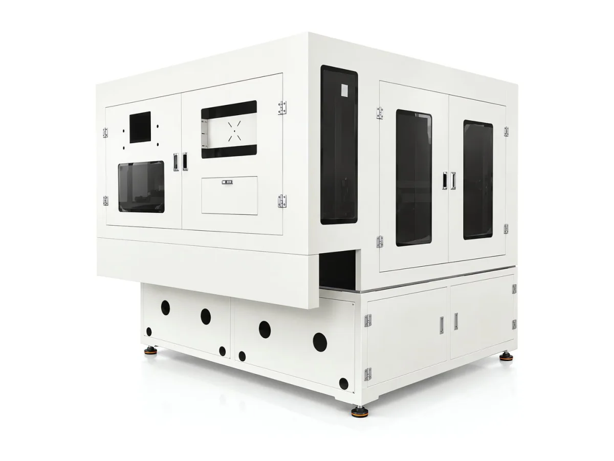
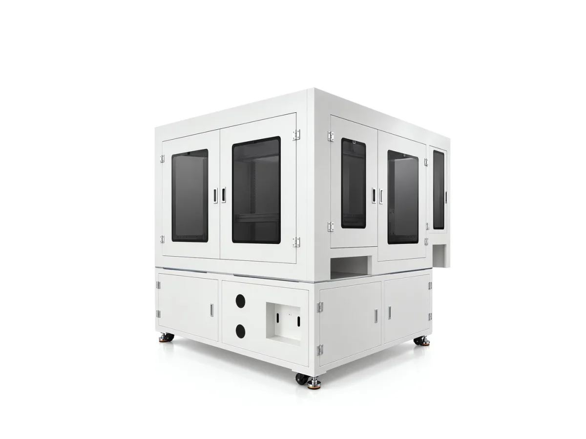
Cut-piece inspection has no standard machine model. The same vision core can be built as a benchtop off-line inspection machine or an in-line material-passing station, or integrated into the automation line after the cutting machine or ahead of sewing. Below we first look at the complete machine formats, then at a unified specification basis, and finally at the real imaging differences between materials at the same station.
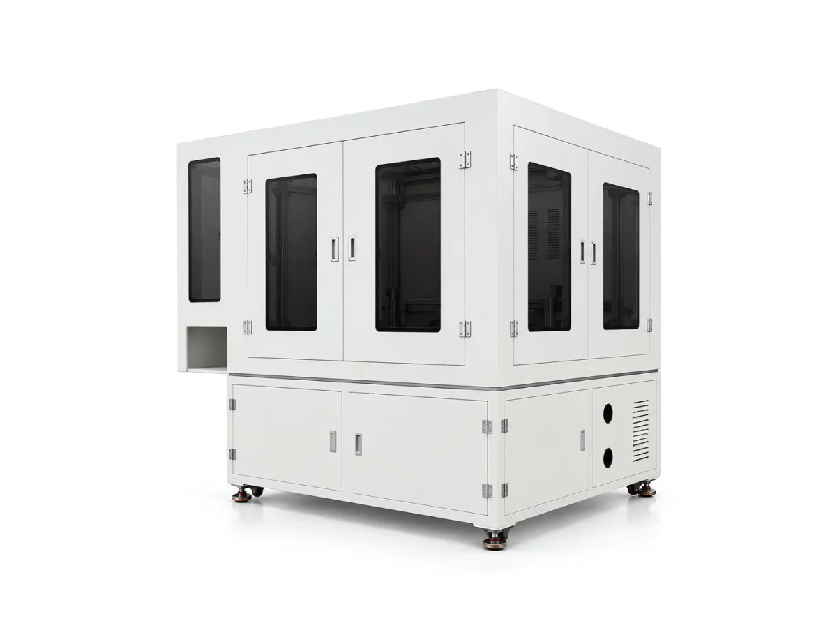
Unified Parameter Conventions
The table below is the template of specifications used uniformly across EEK AI visual inspection equipment. For any item marked "determined by project" or "determined by sample validation", a specific value can only be filled in after validation on actual samples — this page makes no numerical commitment that is not based on samples.
| specifications | Content |
|---|---|
| Brand | EEK |
| Product name | AI visual inspection equipment |
| Product model | Project Customization |
| Inspection Method | AI vision / machine vision |
| Imaging Method | Area-scan / line-scan / multi-view / 3D |
| Inspection Objects | Determined by industry and product |
| inspection scope | Appearance / dimension / defect / form and position |
| inspection accuracy | Determined by sample validation |
| Inspection Speed | Determined by the product and line cycle time |
| software system | EEK visual inspection software |
| algorithm | Traditional vision / AI / 3D algorithms |
| Data Interface | PLC / industrial communication / data systems |
| Origin | Suzhou |
| Equipment Type | In-line inspection / off-line inspection / automated inspection |
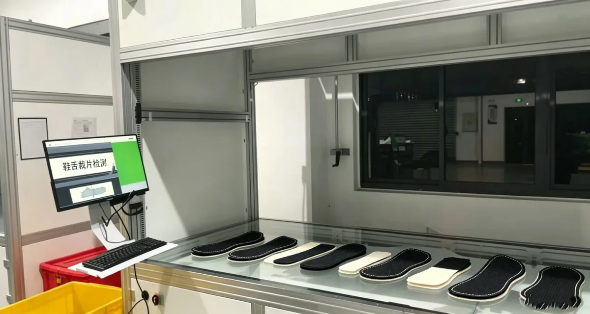
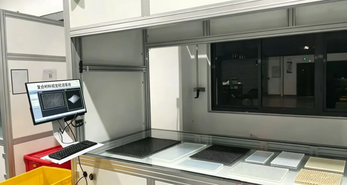
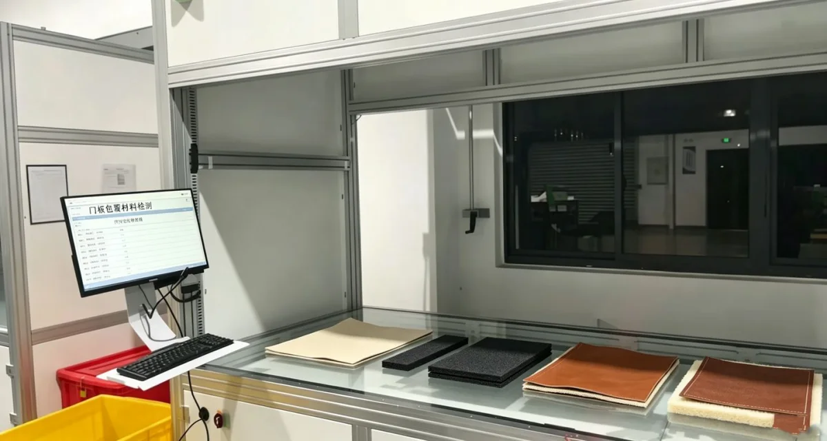
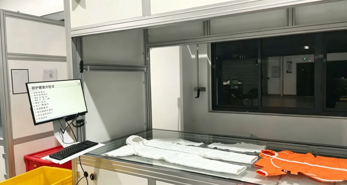
On-Site Imaging of Different Cut Pieces
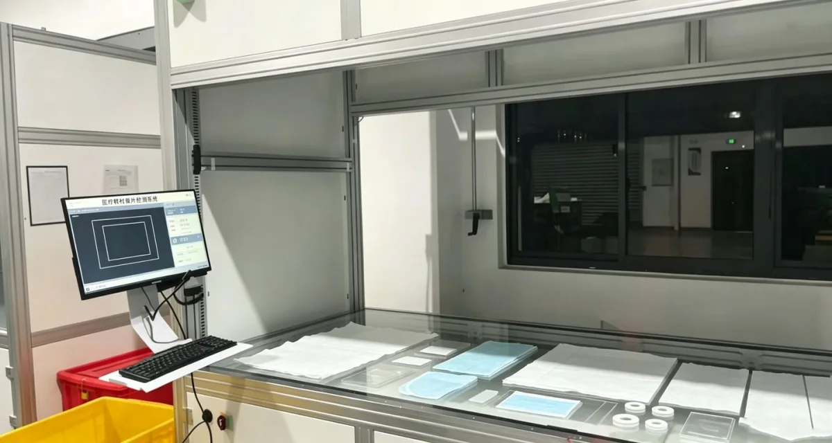
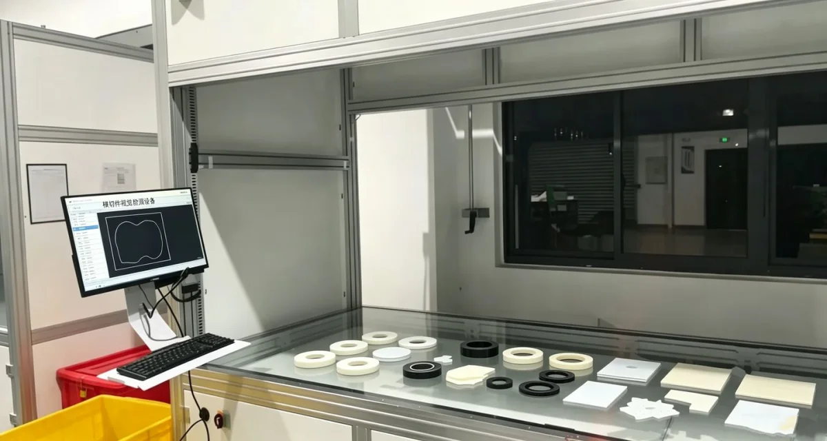
The following images are live imaging records from the same inspection station, showing cut pieces of different materials and colors. Orange elastic fabric, white non-woven material, dark fabric, blue fabric, gray sheet material, denim and leather-type materials all show completely different contrast under the same light source— Illumination and algorithm recipe calibration must be performed separately for each material. This is also why this type of solution insists on "one recipe per material" and does not use generic configurations.
Applicable Industry
Which Industry These Solutions Are Installed In
This Category Document Checklist
Confirmed items and outstanding items
| Information Item | Description | Status |
|---|---|---|
| 6 flexible material solution pages already exist | Cut pieces / roll material / sheets / die-cut parts / composite materials / flexible materials | Existing |
| Maximum cut piece size and area | Determines camera count and the image-splitting scheme | To be added |
| Material feed speed and target cycle time | Determines the sampling frequency and trigger mode | To be added |
| Minimum detectable defect size | Determines resolution and field of view; must be validated by measurement | To be added |
| Material type and grammage / thickness | Determines illumination and feed mechanism | To be added |
| Inspection standard and over-rejection tolerance | Recommended to be defined quantitatively by the customer's quality department | To be added |
| Site mechanism conditions | Tension control, web guiding, available space and mounting position | To be added |
| Interlocking Method | Cutting machine / sorting / marking mechanism and PLC communication method | To be added |
Common Question
Common Questions About This Type of Solution
Which materials is the cut-piece inspection vision solution suitable for?
is aimed at Flexible sheet materials: fabrics such as knit, woven, denim and mesh, leathers such as genuine leather, PU synthetic leather and microfiber synthetic leather, non-woven fabric, TPU laminated fabric, and carbon fiber prepreg, fiberglass, foam, EVA and PET / PI film. The optical characteristics of different materials vary widely, so the lighting method must be selected per material — a single configuration cannot be applied universally.
Do roll material and cut pieces require different equipment?
The imaging logic differs: web material runs continuously, so a line-scan camera can image at even intervals with natural area stitching; cut pieces are loaded discretely, so an area-scan camera combined with positioning is more suitable. If both are present on one line, the usual approach is two stations imaging separately while sharing the same software and judgement logic.
Flexible materials stretch during feeding; is dimensional inspection still accurate?
This is a real limitation. Tension fluctuation distorts dimensional measurement, so dimensional inspection must first stabilize tension mechanically, and where necessary apply synchronous marks or real-time compensation at the inspection position, and compare the same batch of samples in both static and running states during acceptance. If that cannot be achieved, it is recommended to move dimensional items to offline sampling inspection and keep only appearance defects inline.
What is the smallest defect that can be detected?
To be added. It depends on the field of view and camera resolution, as well as the contrast between defect and background. Low-contrast defects (such as foreign matter of the same color or slight color difference) may be unstable to detect even when they are not small. We recommend providing actual defect samples and taking the measured sample-trial conclusion as final.
Will there be many false calls (over-rejection)?
The normal texture of flexible materials itself generates a large number of suspicious signals, so The quality of texture suppression directly determines the over-rejection rate. A workable approach is to first suppress the periodic weave texture and print using background modeling or frequency-domain methods, then judge the defects; at the same time, set the threshold according to the asymmetric costs of escape and over-rejection. The specific over-rejection rate can only be given after trial runs with the customer's real samples in batch.
How do inspection results interlock with the cutting machine or sorting?
The result can be output by cut-piece position and NG pieces picked out with a marking, spraying or sorting mechanism; the defect coordinates can also be sent back to the nesting software so that it re-nests while avoiding the defects and improves material utilization. The specific method depends on the site equipment and communication conditions.
What is the difference between AI vision and conventional machine vision?
Traditional machine vision is better suited to clear rules inspection: dimensions, contour, position, presence/absence and hole position, with calibratable, explainable results. AI vision is better suited to Rules cannot express it clearly defects: complex appearance, texture variation and irregularly shaped defects. In cut-piece inspection the two are almost always combined — contour and dimensions use traditional algorithms to stay quantifiable, while surface defects use AI to cover interference from weave and prints. Using AI for everything, or forcing traditional algorithms to handle everything, usually does not produce stable results.
What inspection accuracy can be achieved?
accuracy cannot be given in isolation from product size, camera field of view, defect size, material characteristics and the inspection environment. With the same camera, doubling the field of view doubles the real-world size represented by a single pixel. This page therefore does not give an isolated accuracy figure—the workable approach is to provide actual defect samples and use measured sample trial results to confirm whether this configuration can cover your smallest defect.
How many samples does an AI model need?
It depends on the defect types, product consistency and inspection requirements; there is no universal number. Actual projects usually start with sample validation: Use a small number of real defect samples to confirm "whether the defects can actually be separated in the image," then determine the model training and validation plan accordingly. Samples must cover the morphological distribution of real defects; a model trained on only a few ideal samples is often unusable on site.
Can we run a vision validation first?
Yes, and this is the recommended first step. For projects involving new products, new materials, or defect acceptance criteria that are not yet fully defined, we recommend starting with Laboratory visual validation: Confirm the imaging method, defect separability, judgement thresholds and cycle time feasibility, and only then decide the optics, algorithm, software and automation solution. Skipping this step and specifying equipment directly carries high risk.
Can It Still Be Used After the Product Model Changes?
Yes. The vision software builds an independent recipe for each product; when changing models, calling up the corresponding recipe switches the inspection areas, dimensional specifications, defect thresholds, and AI models without reprogramming. A new recipe requires one on-site sample acquisition for calibration; if the production line itself has barcode scanning or work-order information, recipe recall can even be automated.
Submit sample testing
Send us the workpiece, defect samples, inspection requirements and production line cycle time, and our solution engineer will determine which category of inspection problem it is and give recommendations on the imaging method and configuration.
Submitted successfully
We have received your sample testing request. A solution engineer will contact you within 1 business day via contact you.
Need to assess imaging conditions, defect criteria and cycle time item by item? Go to the Full Requirement Assessment →
Not Sure Which Category?
Send us the workpiece, defect samples and inspection requirements, and a solution engineer will determine which category of inspection problem it is and give recommendations on the imaging method, algorithm route and equipment configuration.