Defect and Scratch Inspection for Surface Quality
Detects scratches, dents, stains and colour deviation on machined, moulded and coated surfaces, with the illumination chosen for the material.
This Category positioning
Surface defect inspection of flat and near-flat formed parts: first make the defect form a clear image, then separate it from the normal texture, and only then make the judgement
This solution is designed for Flat stamped parts, sheet metal parts, powder metallurgy parts, die castings, ceramic parts and automotive components flat-surface appearance quality inspection, combined with 2D area-scan vision, 2D line-scan vision, 2.5D surface topography inspection, 3D measurement, and AI vision algorithms, covering surface defects such as scratches, scuffing, indentations, pits, pockmarks, blowholes, sand holes, burrs, chipped corners, short shots, cracks, discoloration, oil stains and dirt. From image acquisition, defect recognition and dimensional inspection to OK/NG judgement and data recording, it provides complete automated visual inspection capability for flat and near-flat formed parts.
Stamped parts, sheet metal parts, powder metallurgy parts and automotive parts usually show different types of surface quality problems during production. These defects share one characteristic: The product itself may show no obvious color change, yet its surface topography has already changed. For example, shallow scratches show little color change, slight indentations have a gray level close to that of the normal surface, and tiny pits cover only a very small area; powder metallurgy parts have complex surface texture of their own; die castings have pitting, porosity and rough texture on the surface; stamping can also produce tearing, indentations and local deformation, while reflections on metal surfaces affect the stability of conventional 2D images.
Therefore, visual inspection of flat metal parts is not simply "taking a photo". What really needs to be solved is: How to image defect characteristics consistently and then judge them accurately with algorithms. This is also why this type of solution puts "imaging method selection" before "algorithm selection" — the same scratch may be invisible under diffuse light, but becomes very obvious under low-angle or directional illumination.
In actual projects, solutions of this kind are usually configured according to Product dimensions, production method, surface material, defect types, and inspection cycle time Combining vision technologies: for flat products that are stationary or fed intermittently, prefer 2D area-scan; for long, large or continuously moving products, consider 2D line-scan; when 2D struggles to resolve topography-type defects such as shallow scratches, tiny pits and indentations, add 2.5D surface topography inspection; when measurement items such as flatness, warpage and height difference are required, introduce 3D; when defect shapes vary widely and are hard to enumerate with rules, use AI defect inspection to supplement the judgement capability.
inspection Pain Points
Why surface defects on flat parts are hard to inspect
The problems with manual visual inspection are low efficiency and inconsistent inspection standards, with the judgement scale drifting after long working hours. Ordinary vision solutions, meanwhile, are easily disturbed by material, texture and reflection in the inspection of fine surface defects. The table below lists the most common difficulties in projects of this type.
Defects Have No Clear Color Difference
Shallow scratches show little color change and light indentations have a gray level close to that of the normal surface, so a single gray threshold can hardly separate them reliably.
Small Defect Scale
Tiny dents, pitting and pinholes have very small areas; under a field of view and resolution that do not match, only a few pixels remain after imaging.
The Normal Texture Is Complex in Itself
The porosity and sintering texture of powder metallurgy parts and the rough surface of die castings both produce signals similar to defects, so "normal texture" must be distinguished from "real defects".
Metal Surface Reflections
Highly reflective areas on polished surfaces, platings and aluminum parts make the gray-level distribution of 2D images unstable, so the imaging method must be specifically designed.
Topography defects cannot be seen
The core characteristic of defects such as indentations, bulges and local deformation is not color but a change in surface height, which appears very weakly in ordinary 2D images.
Combined Inspection of Multiple Items
A single workpiece often has multiple requirements at once — appearance defects, dimensions, hole positions, characters, and so on — so several classes of judgement must be completed on one machine.
Core Technologies Solution
2D area scan + 2D line scan + 2.5D surface topography + 3D measurement + AI defect inspection
Depending on product dimensions, production method, surface material, defect types and inspection cycle time, a project can choose different vision technologies, or combine several of them on the same workpiece.
01 | 2D Area-Scan Visual Inspection
Suitable for static and intermittent flat product inspection, using an industrial camera to acquire high-resolution images of the product surface.
- Inspection: off-color, oil stain, dirt, short shot, chipped corner, visible scratch
- Inspection: characters, printing, hole position, contour, dimensions
- Applicable: stamped parts, sheet metal parts, flat metal parts, automotive parts, powder metallurgy parts, ceramic parts
02 | 2D Line-Scan Visual Inspection
For long, large and continuously moving products, it performs continuous acquisition of long products that an ordinary area-scan camera cannot easily cover in one shot.
- Process: continuous motion → line-scan acquisition → image stitching
- Process: defect recognition → OK/NG judgement → automatic rejection
- Applicable: long stamped parts, metal sheet, continuously produced products, large sheet metal parts, web materials and long-format products
03 | 2.5D Surface Topography Visual Inspection
When 2D cannot resolve a defect clearly, vision looks further into the surface topography. Surface topography features are acquired through specific optical imaging methods.
- Available data: height information, normal information, curvature information
- Obtainable: shadow features, texture features
- Applicable: shallow scratches, slight indentations, tiny pits, slight raised areas, pitting and localized surface anomalies
04 | 3D Dimension and Geometric Inspection
For measurement items such as flatness, warpage, local deformation and height difference, quantitative judgement is completed using point cloud data.
- Algorithm: point cloud preprocessing, outlier filtering, ROI extraction
- Algorithm: datum plane fitting, multi-point height sampling, Z-direction deviation calculation
- Output: 3D data, measurement points, height values, flatness results, and out-of-tolerance positions
05 | AI Defect Inspection
When defect forms are highly variable and difficult to describe exhaustively with rules, deep learning models perform the recognition and classification.
- AI defect classification, AI object detection
- AI semantic / instance segmentation
- Anomaly detection, 2D and 3D data fusion
06 | Multi-Station Fusion
2D, 2.5D, 3D and dimensional measurement are assigned to different stations, completing multiple judgement types within one machine.
- Independent triggering of multiple cameras and light sources
- Results merged and output uniformly as OK / NG
- Can interlock with loading/unloading and sorting mechanisms
inspection Scope
Common Inspection Items and Preferred Imaging Methods for Flat Formed Parts
Scratch | scuff | indentation | dent | pitting | blowhole | sand hole | burr | chipped corner | short shot | crack | discoloration | oil stain | dirt | surface anomaly
| Defect Category | Typical Defects | Preferred Visualization / Inspection Method |
|---|---|---|
| Linear Damage | Scratches, scores, drag marks, scuffs, gouges | Low-angle or stripe light reveals them; diagonal scratches need multi-directional illumination, combined with 2.5D topography when necessary |
| Deformation | Indentations, crush marks, pits, bulges, local deformation, warping | 2.5D topography / fringe light; height and flatness measurement items switch to 3D point cloud |
| Surface Contamination | Oil stains, dirt, foreign matter, rust spots | Diffuse light / coaxial light; must be distinguished from the material's own normal texture |
| Chromaticity | Off-color, color difference, oxidation discoloration, local darkening | Stable light source + white balance datum; the acceptable color difference range must be defined first |
| Casting | Blowholes, sand holes, cold shuts, shrinkage depressions, flow lines | Combination of diffuse and low-angle light; shallow pits are evaluated with 2.5D |
| Powder Metallurgy Category | Short shot, powder loss, chipped corners, delamination, abnormal porosity, pitting | 2D + 2.5D + AI combination, with the focus on separating normal porosity from abnormal defects |
| Edge | Burrs, edge burrs, flash, chipped edges, missing corners, gate residue | Backlight or coaxial light for contour measurement; burr-height items combined with 2.5D/3D |
| Crack | Cracks, micro-cracks, delamination cracking | High resolution + side light; must be distinguished from scratches and machining marks |
| Process | Missing material, missed punch holes, stamping anomalies and abnormal machining marks | 2D contour and area analysis; hole position items switch to measurement algorithms |
| Dimensional | Hole diameter, hole spacing, outer diameter, inner diameter, length, width, contour dimension | Measure after calibration, and note how fixturing, positioning and material travel affect the measurement |
inspection Object
Common product, material and part types inspected
The following groups are based on material and part type. Workpieces in the same group can often reuse the same optics and algorithm route; products across groups usually need the imaging method evaluated separately.
Flat Stamped Parts / Sheet Metal Parts
Stamped panels, chassis brackets, automotive structural parts, sheet metal parts, metal housings, stamped gaskets and metal brackets.
Powder Metallurgy Parts
Powder metallurgy structural parts, sintered parts, automotive parts, oil-impregnated bearings, gears and precision metal parts.
Die Castings
Aluminum alloy die castings such as automotive housings, brackets, valve bodies, motor housings and metal structural parts.
Ceramic and Flat Structural Parts
Ceramic substrates, ceramic structural parts, insulating parts, ceramic valve plates, and precision ceramic parts.
automotive parts
Stamped parts, sheet metal parts, die castings, powder metallurgy parts, metal brackets, structural parts and decorative parts.
Other Precision Metal Parts
Precision machined parts, hardware and fasteners — parts whose appearance is mainly flat or nearly flat.
View Inspection Highlights by Defect Type
View Application Solutions by Workpiece
Typical defect
Which defects this type of solution mainly targets, and what to watch for in each case
| defect | Typical Manifestations | Inspection Focus Points |
|---|---|---|
| Scratch / Scuff | Surface linear damage with clear directionality | Low-angle light reveals the feature; diagonal scratches may be masked by directional illumination, and shallow scratches on dark glossy materials require dedicated validation |
| Indentation / Compression Damage | Shallow dents formed by local pressure, with little color change | The gray-level difference in 2D is small, so 2.5D topography is often used for confirmation; it must be distinguished from normal process embossing |
| Pits / Bulges | Local height anomaly, the area may be very small | Topography features rather than color features; for very small areas, the field of view and resolution must be confirmed first |
| Pitting / Sand Holes | Dense small dot-like surface anomalies | Distinguishing these from normal material grain and residual molding sand is the main source of false calls |
| Porosity / Cold Shut | Holes and flow marks formed by the casting process | Combination of diffuse and low-angle light; shallow porosity needs 2.5D evaluation |
| Burr / Edge Chipping | Excess material at the edge or local damage | Backlight or coaxial light for contour measurement; burr height requires 2.5D/3D |
| Short Shot / Missing Punched Hole | Missing material or skipped process step | Compare with the normal contour; note false calls caused by workpiece placement deviation |
| Crack / Micro-Crack | Thin, discontinuous linear defects | Requires high resolution + side lighting, with attention to distinguishing them from scratches and machining marks |
| Discoloration / oxidation color difference | Chromaticity deviation within a part or between batches | Requires a stable light source and a white balance reference; the quality department should first define the acceptable color difference |
| Oil stains / dirt / foreign matter | Surface deposits or embedded particles | Distinguishing them from the material's natural texture is essential; same-color foreign matter has low contrast and requires dedicated illumination |
inspection Capabilities
From single-defect inspection to comprehensive multi-item judgement
Products such as automotive parts have high requirements for appearance and manufacturing quality, and visual inspection can cover the following five categories of judgement on a single machine.
appearance inspection
Recognition and classification of surface defects such as scratches, impact marks, compression marks, pits, dirt, off-color, foreign matter and burrs.
dimensional inspection
Measurement items such as length, width, outer diameter, inner diameter, hole diameter and hole spacing, judged against the upper and lower tolerance limits after calibration.
Contour Inspection
Contour comparison and deviation calculation for the outer contour, edge position, and hole position relationships.
defect inspection
Judgement rules are established by defect type, area, length, width and position, and a defect grade is output.
character recognition
Presence of characters, missing characters, abnormal characters and content recognition, used to confirm model and batch.
Form and Position Inspection
Flatness, warpage, height difference and local deformation are handled through 3D point clouds and datum plane fitting.
AI vision algorithm
Rule-based algorithms and deep learning used in combination according to defect characteristics
Traditional vision algorithm
Suited to inspection items with regular shapes and quantifiable criteria, where results are explainable and parameters traceable.
- Edge extraction and contour analysis
- Sub-pixel dimensional measurement, circle fitting, line fitting
- Blob region analysis, gray level/color difference inspection
- Scratch inspection, foreign matter and dirt inspection, burr inspection
- Defect region segmentation with area, length and width calculation
Deep Learning Algorithms
Suited to defects with highly variable shapes that are hard to cover with exhaustive rules, and requiring sample training and maintenance.
- AI Defect Classification
- AI Object Detection
- AI semantic / instance segmentation
- Anomaly detection (modeling the normal state when defects are hard to enumerate)
- OCR character recognition, 2D and 3D data fusion
In the same project, the two types of algorithms are usually used in parallel: Rule-based measurement items go to traditional algorithms, ensuring stable values and traceability; Defects of varying shape are handled by deep learning, with the model performing recognition and classification; the two results are merged and output as a single OK/NG.
vision software Platform
The inspection software completes acquisition, judgement, recording and external communication
Recipe and Parameter Management
Product recipe management and inspection parameter management, supporting fast switching between multiple products.
Permission Management
Tiered permissions for operation, debugging and maintenance keep specifications from being changed at will.
Statistics and Reports
OK/NG statistics, defect classification statistics, report output.
Image and Result Retention
Defect images are saved and inspection results can be queried, making re-judgement and review easier.
data traceability
Images, results and product information are linked together to support historical queries.
External Interfaces
PLC communication and MES / production system data interfaces can output OK signals, NG signals, defect types, inspection results and measurement data.
Technology Architecture
Optical imaging layer · algorithm layer · vision software layer · automation control layer
The product is not a single "camera inspection" but a four-layer coordinated system: the optics layer determines whether a defect can be imaged, the algorithm layer determines whether it can be resolved, the software layer handles judgement and recording, and the automation layer handles integration with the production line.
First Layer: Optical Imaging Layer
Configure 2D area scan, 2D line scan, 2.5D vision, and 3D line laser according to the product characteristics, and select low-angle, coaxial, diffused, backlight, or pattern light sources according to the defect type.
Layer 2: Algorithm layer
A combination of multiple algorithms is established: sub-pixel measurement, contour analysis, region analysis, grayscale and color difference, defect segmentation, and AI classification / inspection / segmentation and anomaly detection.
Third Layer: Vision Software Layer
Unified management of product recipes, camera acquisition, algorithm calls, parameter management, inspection results, defect classification, data storage, image traceability and report statistics.
The Fourth Layer: Automation Control Layer
Integrates with the PLC, loading and unloading mechanism, conveyor mechanism, locating mechanism, sorting mechanism and MES / data system to complete triggering, sorting and data return.
inspection Method
What exactly is the difference between 2D and 2.5D
2D mainly looks at what changes on the surface; 2.5D goes further and looks at whether the surface has height changes.
| defect | 2D Image Representation | 2.5D Performance | Result |
|---|---|---|---|
| oil stain | Gray level changes | Surface height remains essentially unchanged | Visible in 2D |
| Pits | There may be only a very weak grayscale change | Clear surface topography changes can be observed | 2D + 2.5D Is More Reliable |
| scratch | May appear as a line of abnormal gray level | Can further analyze the surface topography changes caused by scratches | Select the combination according to darkness and material |
Therefore, for products such as flat stamped parts and formed metal parts, the appropriate option can be selected according to the actual defect characteristics 2D, or 2D + 2.5D Combined Inspection. The basis for judgement is not "which technology is more advanced" but whether this type of defect appears in the image mainly as a grayscale difference or mainly as a topography difference.
When to Use 2D
The defect shows a clear difference in grayscale, color or contour from the product background, for example oil stains, rust spots, obvious short shot, obvious chipping, off-color and abnormal hole position.
When to Add 2.5D
The defect features are mainly height variations, such as shallow scratches, tiny dents, indentations, slight bulges and surface topography anomalies.
When to Use 3D
Quantitative geometric values must be output, such as flatness, warpage, height difference and local deformation.
inspection workflow
- 01 Collect real OK / NG samples (including borderline samples)
- 02 Lighting and imaging trials to confirm that defects can be imaged
- 03 Define the inspection zone and the smallest defect size that must be detected
- 04 Label samples and train / tune parameters
- 05 Trial run at batch scale and count escapes and over-rejections
- 06 Adjust the threshold according to the cost asymmetry
- 07 Go live while keeping a channel for review and retraining
Equipment and complete machine
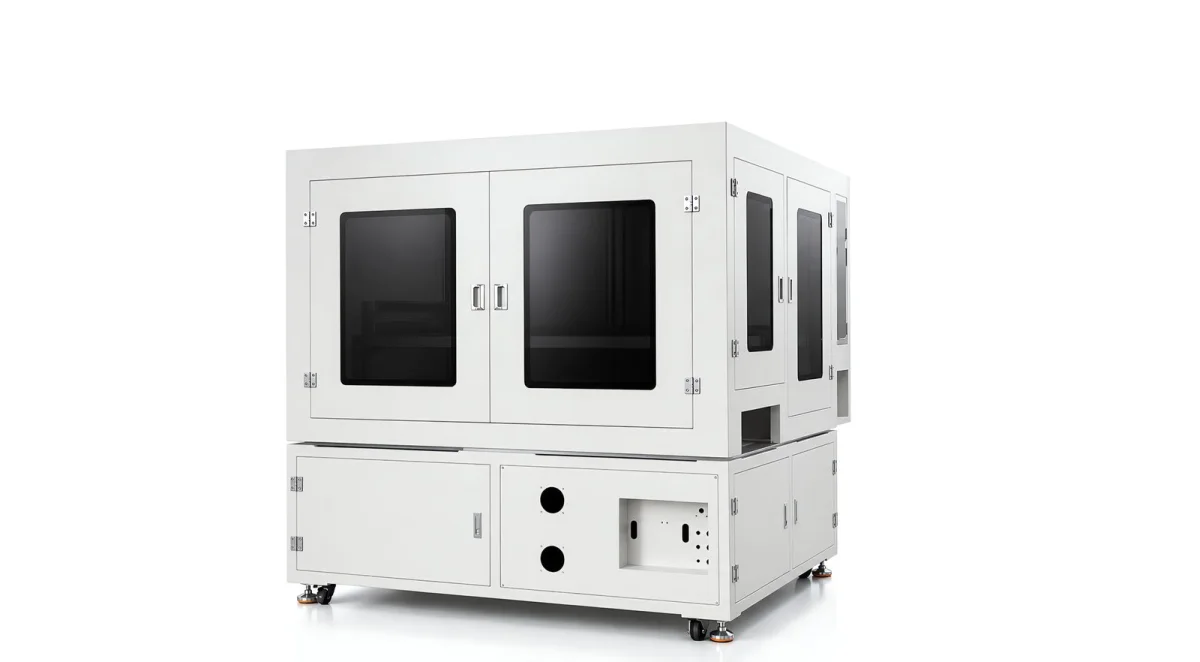
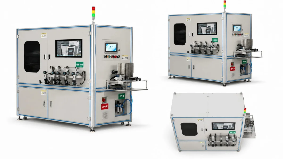
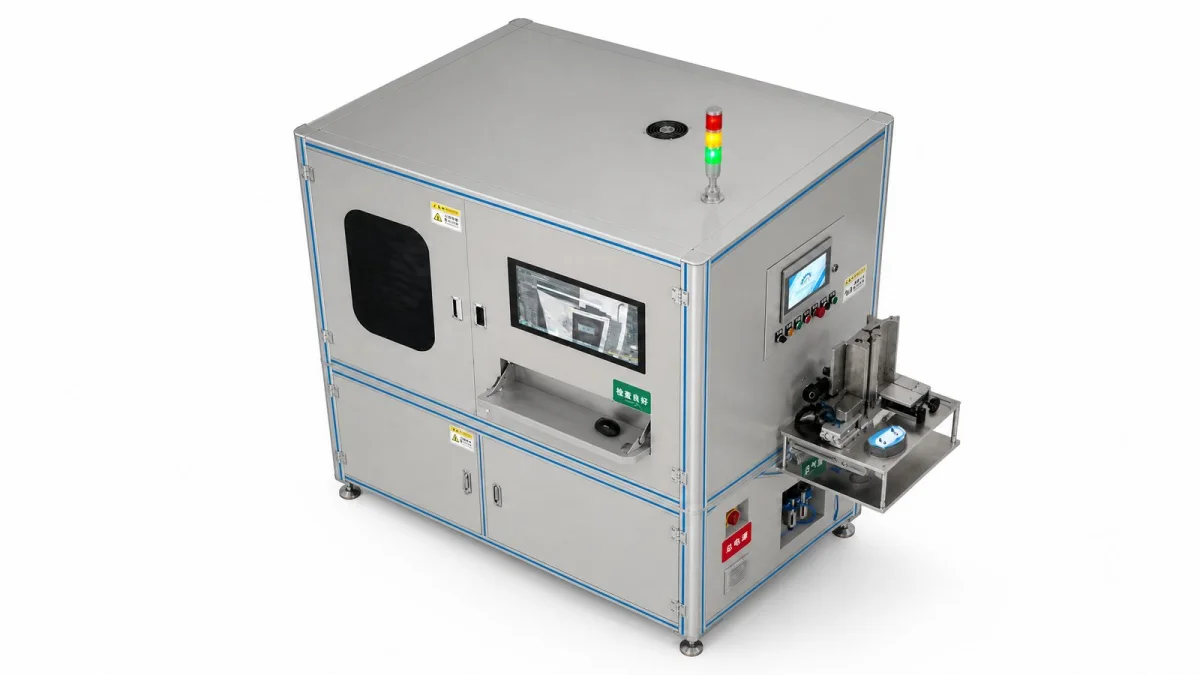
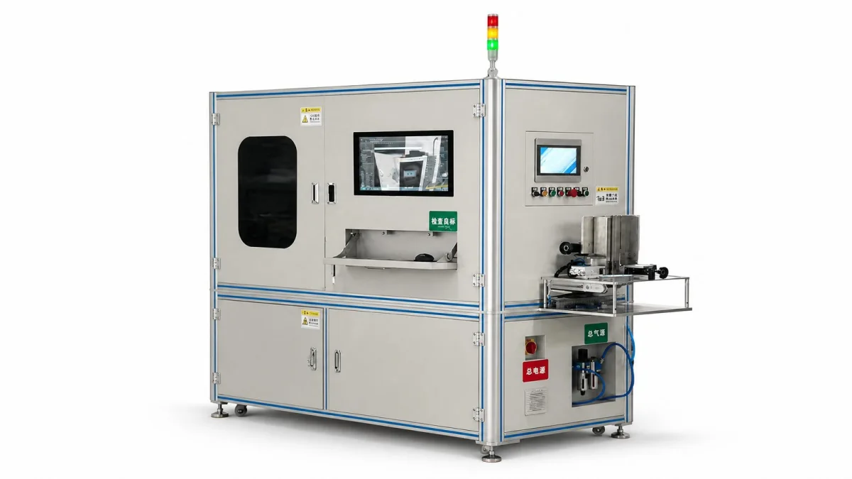
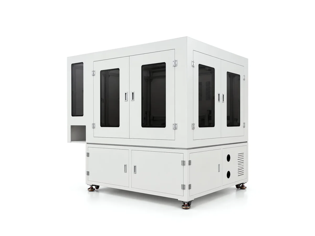
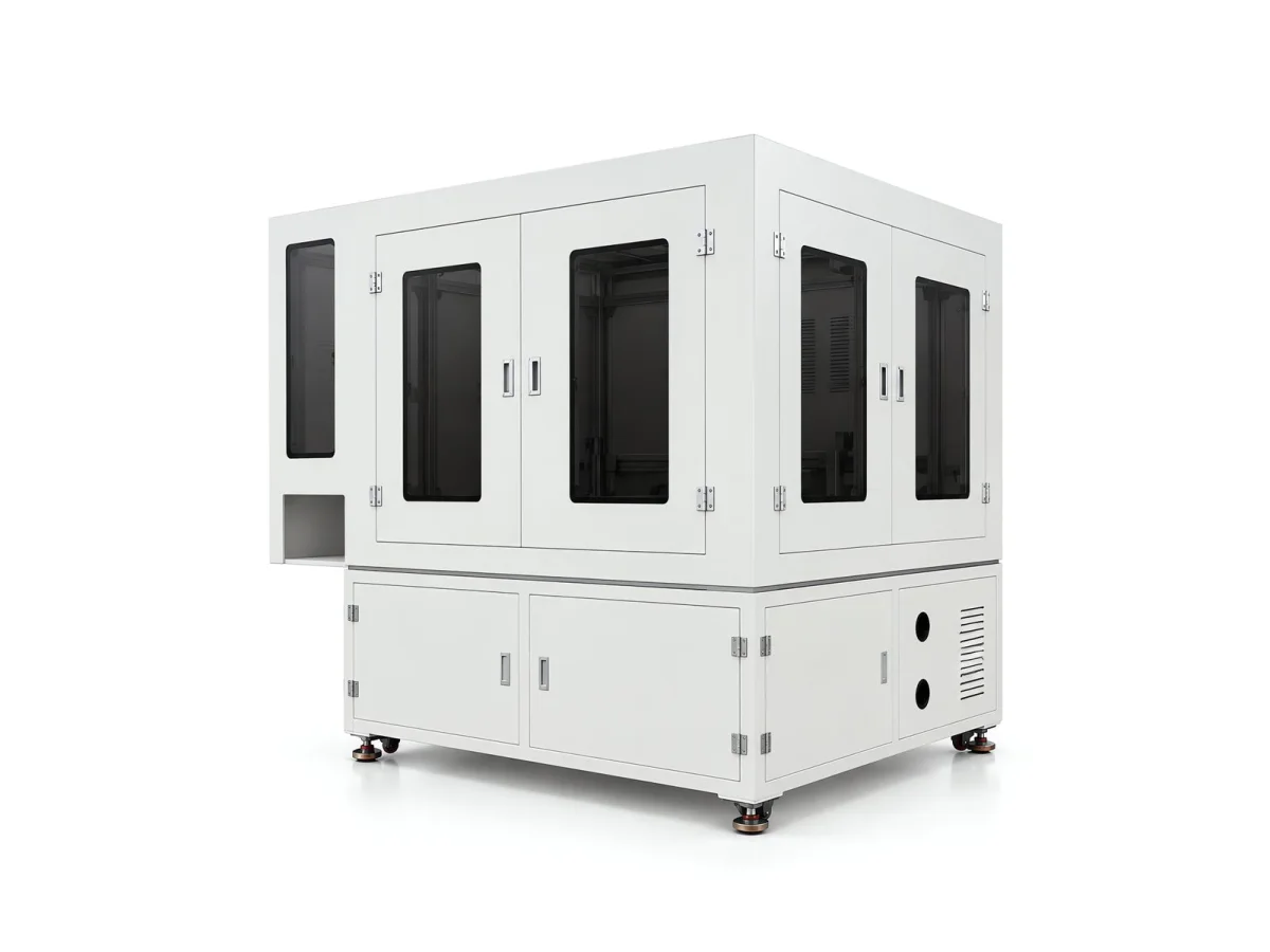
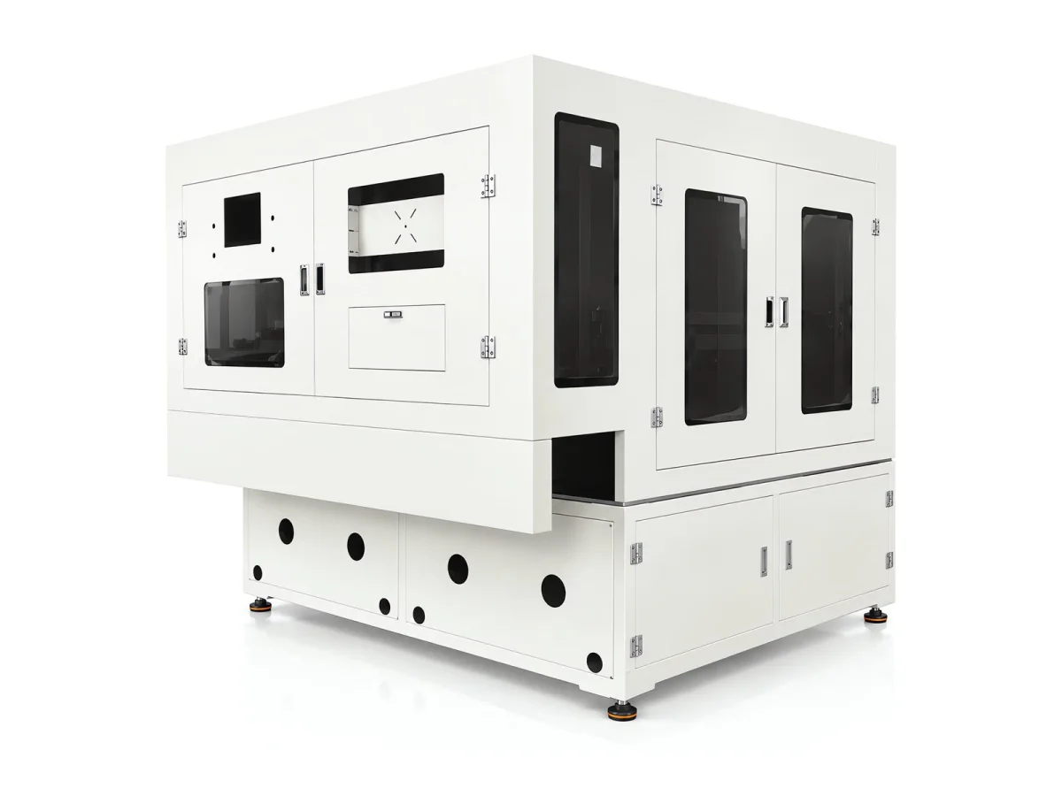
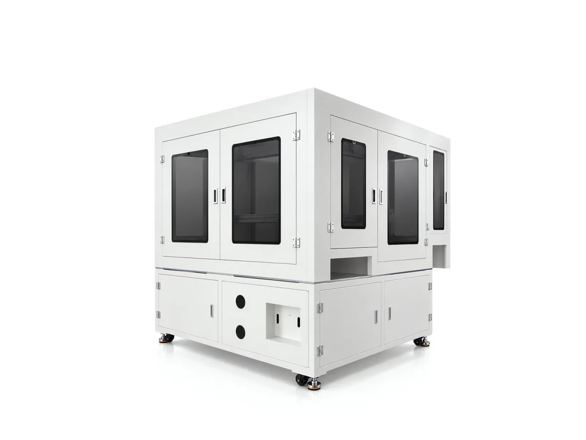
Flat-Part Visual Inspection Equipment Configuration and Station Structure
The table below lists the equipment configurations commonly used for this type of solution. The cabinet structure, number of stations, and infeed/outfeed method are determined by the workpiece loading method, the number of inspection items, and the line cycle time: small products with a single inspection item usually use a single-station machine; products with multiple inspection items have the stations split by item; and products that require linked production are equipped with belt conveying or a rotary-table infeed/outfeed mechanism.
Applicable Industry
Typical Industries These Solutions Are Installed In
Typical Applications combination
Solution combinations by inspection purpose and their technical routes
| Solution | Core Applications | Core Vision Technologies | Core Algorithms |
|---|---|---|---|
| Solution 1 | Combined inspection of flat stamped parts | 2D / 2.5D / 3D | Defect + Measurement |
| Solution 2 | Scratch Defect Inspection | 2D / 2.5D | Defect Segmentation + AI |
| Solution 3 | Hole Diameter Measurement | 2D area scan | Sub-Pixel Measurement |
| Solution 4 | Flatness Inspection | 3D | Point cloud + plane fitting |
| Solution 5 | Burr Edge Inspection | 2D / 3D | Contour Analysis |
| Solution 6 | Presence/absence / missing part inspection | 2D | Template Matching + AI |
| Solution 7 | Powder Metallurgy Inspection | 2D / 2.5D / 3D | Defect + Measurement |
| Solution 8 | Inspection of flat areas on die castings | 2D / 2.5D / 3D | ROI + Defect Algorithm |
| Solution 9 | Ceramic flat part inspection | 2D / 2.5D | Defect Segmentation + AI |
| Solution 10 | Combined inspection of automotive parts | 2D / 2.5D / 3D + AI | Multi-Algorithm Fusion |
Implementation Workflow
Ten steps from project overview to delivery
- 01 Project overview: define the workpiece, material and inspection purpose
- 02 Inspection requirements: confirm the inspection category and acceptance criteria item by item
- 03 Overall Technical Architecture: Determining the Number of Stations and the Inspection Division of Work
- 04 Optical imaging solution: light source, lens and camera selection with illumination validation
- 05 Algorithm plan: division of labor between rules and AI, plus parameters
- 06 Software plan: recipes, UI, statistics, and interfaces
- 07 Automation solution: loading and unloading, conveying, sorting and PLC integration
- 08 Performance validation: confirm item by item against the validation list
- 09 Risks and countermeasures: boundary samples, special materials and cycle time risks
- 10 Project delivery: acceptance, training, and operation and maintenance
Project Performance Validation Items
When the project is formally implemented, the following validation items are established according to the customer's specification, and the validation conclusions are subject to the samples and test conditions jointly confirmed by both parties.
| Validation Item | Validation Content |
|---|---|
| Imaging Accuracy | Pixel accuracy, field of view, defect visibility |
| inspection capability | OK / NG Sample Validation |
| Measurement Accuracy | Standard parts and repeated measurement |
| Repeatability | Multiple consecutive acquisitions |
| escape rate | NG Sample Validation |
| Over-rejection Rate | OK Sample Validation |
| CT | Complete inspection cycle per part |
| stability | Continuous operation test |
| data traceability | Linking images, results, and product information |
Why Choose EEK
Optics, algorithms, software and automation: all four layers delivered by the same team
Validate Illumination First, Then Discuss Algorithms
In projects of this kind the reason for failure is usually not the algorithm but the fact that the defect never shows up in the image at all. We make the imaging experiments solid at the solution stage and only define the algorithm route after confirming that the defect can be imaged.
Combine Technologies by Defect Characteristics Instead of Forcing a Single Solution
Do not add 2.5D where 2D is sufficient; introduce 2.5D or 3D only when topography judgement is needed, and bring in AI when defects are hard to enumerate. Technology selection is subordinate to inspection purpose and cost.
No Fabricated Metrics, Sample Trial Results Prevail
Specifications such as accuracy, cycle time and escape rate are strongly tied to the workpiece and site conditions; we do not make numerical commitments that have not been measured, but run a sample trial first and then jointly confirm the achievable level.
Equipment and Automation Delivered as One Package
Optics, algorithms, software, loading and unloading and PLC integration are handled by the same team, avoiding the interface finger-pointing common when vision and production line belong to different suppliers.
This Category Solution
Other solution pages for the same type of problem
Solutions in this category are subdivided by inspection purpose and workpiece type. The table below lists the related solution pages already built; slots for further workpiece-specific solutions are reserved and will be published as the information is completed.
This Category Document Checklist
Confirmed items and outstanding items
| Information Item | Description | Status |
|---|---|---|
| Inspection Objects and Covered Materials | Stamped parts, sheet metal parts, powder metallurgy parts, die castings, ceramic parts, automotive parts | Existing |
| Technical approach and algorithm capabilities | 2D area-scan / 2D line-scan / 2.5D / 3D / AI and software function modules | Existing |
| Implementation process and validation items | Ten-step implementation process and nine performance validation items | Existing |
| Equipment Model Specifications | Outline dimensions, interface definitions, optional configuration list | To be added |
| Defect list and acceptance criteria | Must be quantitatively defined by the customer's quality department, including borderline sample criteria | To be added |
| Real defect samples | OK / NG and borderline samples, in sufficient quantity for training and validation | To be added |
| Minimum defect size to be detected | Determines field of view and resolution; must be validated by measurement | To be added |
| Inspection cycle time and production line conditions | Loading and unloading method, available space and site lighting conditions | To be added |
| Publicly shareable application cases | Publication requires customer authorization | To be added |
| Sample and defect photographs | For replacing the equipment diagram on this page and adding workpiece and defect sample images | To be added |
Common Question
Common Questions About Flaw Inspection of Flat Parts
Why can't surface defects on flat stamped parts be judged from a single photo?
This is because many defects have no obvious color change themselves; only the surface morphology has changed: shallow scratches show little color change, slight indentations have a gray level very close to that of a normal surface, and tiny pits are very small in area. Combined with the surface texture of powder metallurgy parts, the pitting and rough texture of die castings, and the reflections from metal surfaces, the gray level differences in an ordinary 2D image are often insufficient to reliably distinguish defects from normal surfaces.
So what such projects really have to solve comes down to two things: Image the defect characteristics consistently first, then judge them accurately with algorithms.
What exactly is the difference between 2D and 2.5D?
In one sentence: 2D mainly looks at what changes on the surface; 2.5D goes further and looks at whether the surface has height changes. Take oil stains as an example: the gray level changes in a 2D image, but the surface height barely changes. Take a dent as an example: 2D may show only a very weak gray-level change, while 2.5D can reveal an obvious change in surface topography. Take a scratch as an example: 2D may show it as a line of abnormal gray level, while 2.5D can further analyze the surface topography change caused by the scratch.
So 2D, or a 2D + 2.5D combination inspection, can be selected according to the actual defect characteristics.
When is line-scan vision mandatory?
For long products that a conventional area scan camera cannot easily cover in one shot, such as Long stamped parts, metal sheet, large sheet metal parts, and coil and long-format products, line-scan vision can be used for continuous acquisition: continuous product motion → line-scan image acquisition → image stitching → defect recognition → OK/NG judgement → automatic rejection. It is particularly suited to inspection scenarios where the production line runs continuously.
Why are powder metallurgy parts difficult to inspect?
Powder metallurgy parts themselves may have Lots of normal surface texture and pores, so the difficulty of visual inspection is not simply finding "black spots," but distinguishing normal surface texture from the abnormal defects that genuinely affect product quality. Common defects include short shot, powder loss, chipped corner, indentation, crack, delamination, pitting and abnormal porosity. Projects of this kind usually require 2D vision + 2.5D topography + AI algorithms for combined inspection.
Which die casting defects suit 2D, and which require 2.5D?
Common die casting defects include porosity, sand holes, cold shuts, shrinkage depressions, flow lines, flash, burrs, gate residue and scuffs. Among them Obvious surface defects can be inspected with 2D vision; for Shallow pits, local height anomalies, burr height and surface topography changes, so a 2.5D vision approach can be evaluated further.
What is the inspection accuracy?
[To be added] Accuracy depends on the field of view and camera resolution, as well as the contrast between defect and background—at low contrast, even sufficient resolution may not give reliable detection. The correct approach is to first determine the smallest defect size to be inspected, then work back to the field of view and resolution, and finally verify with a measured sample trial.
Can it replace manual visual inspection?
can replace Repeatable appearance judgement, and it is more consistent than manual labor—operators tire and standards drift. But it also has clear boundaries: internal defects cannot be seen by vision, and items that require tactile or destructive testing cannot be handled either. It also needs someone responsible for sample maintenance, threshold adjustment and NG review, so it is not completely labor-free.
What if the over-rejection rate is high after launch?
First clarify whether it is an imaging problem or a judgement problem: Pull up the images of the over-rejected parts and look at them. If a defective part and a normal part look clearly different on the image, it is a matter of thresholds or algorithm parameters; if the two images are almost identical, it means the illumination failed to reveal the difference and the imaging method must be changed. At this step we recommend keeping the original images on file, otherwise the case cannot be reviewed later.
Submit sample testing
Send us the workpiece, the defect samples, the inspection requirements and the line cycle time, and a solution engineer will determine which category of inspection problem it is and provide recommendations on the imaging method, the algorithm route and the equipment configuration.
Submitted successfully
We have received your sample testing request. A solution engineer will contact you within 1 business day via contact you.
Need to assess imaging conditions, defect criteria and cycle time item by item? Go to the Full Requirement Assessment →
Not Sure Which Category?
Send us the workpiece, defect samples and inspection requirements, and a solution engineer will determine which category of inspection problem it is and give recommendations on the imaging method, algorithm route and equipment configuration.