Inspection of Wrapped and Laminated Interior Parts
Inspection of wrapped and laminated automotive interior parts: wrap alignment, seam quality, wrinkles, air pockets and colour match.
This Category positioning
Inspection of wrinkles, blistering, delamination, edge wrapping, and joining on three-dimensional wrapped parts
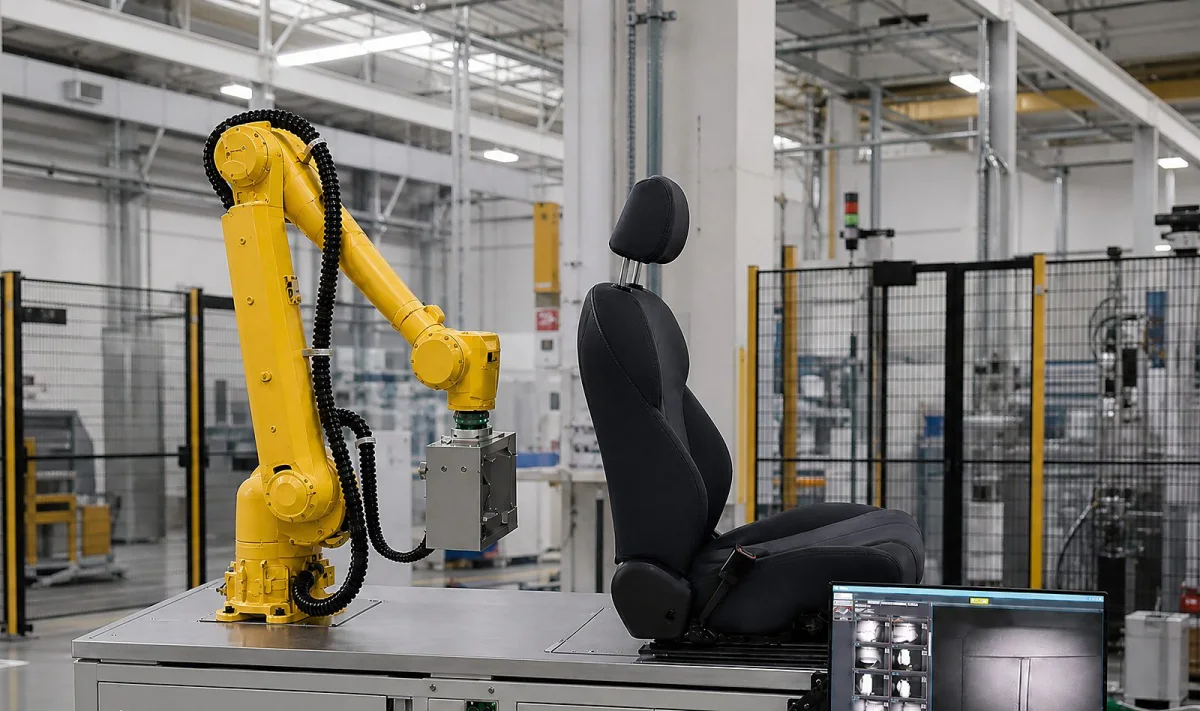
The visual inspection solution for wrapped parts addresses three-dimensional parts in which leather, fabric or film is wrapped over a frame, such as automotive seats, door panels, instrument panels, armrest console lids and center consoles. The most typical defects of such parts are wrinkles, blistering, delamination, incomplete wrapping at corners, color difference and splice misalignment produced during the wrapping process. These are not flat defects but three-dimensional topography problems that follow the undulations of a curved surface, so multi-angle and topography imaging are required, and the key positions of the wrapping process must be fixed as inspection zones.
Defects on wrapped parts differ fundamentally from ordinary appearance defects: It is deformation caused by the process, not a problem with the material itself. With the same piece of leather, different wrapping gestures, stretch amounts, and heating temperatures produce different wrinkle positions and shapes. This means such defects often have no stable morphological features, and a gray-scale threshold on a single image can hardly judge them accurately.
So the focus of this category of solutions is Lock down the key positions of the wrapping process: Corners, bends, grooves and seams, and the areas subject to the greatest stretch — the inspection area and judgement method for these positions are designed separately rather than treating the whole part uniformly. In addition, stripe light or photometric stereo is used to turn topography problems such as wrinkles and blistering into signals that can be judged.
Another special requirement is traceability. Wrapped parts are usually installed in the vehicle interior, and if a mass production problem occurs, it must be traceable back to the specific batch and station, so the binding relationship between inspection results, part identification, and process parameters must be designed in advance.
inspection Pain Points
Why Surface Defects on Wrapped Parts Are Hard to Inspect
Manual visual inspection requires the inspector to repeatedly change the viewing angle around the workpiece; it is inefficient, and the judgement scale drifts after long hours of work. Ordinary vision solutions, in turn, run into the following kinds of difficulty on wrapped parts — their common point is: Whether a defect can be seen depends on the imaging method, not the algorithm.
Defect Sources Come from the Process, Not the Material
Wrinkles, blistering and corners that are not fully wrapped are deformations caused by the wrapping operation. With the same piece of leather, different hand movements, stretch amounts and heating temperatures result in different defect positions and forms, so there is no stable morphological feature to follow.
Curved Surfaces Cause Reflections and Shadows
A three-dimensional part differs greatly in brightness between orientations; the same defect may be obvious at one angle and hidden by highlight or shadow at another, so single-view imaging easily misses defects.
Morphological Defects Are Weak in 2D Images
The core characteristic of defects such as wrinkles, slight blistering and delamination is not color but a change in surface height, which appears very weakly in ordinary grayscale images.
Normal Texture Is Easily Confused with Defects
Genuine leather has natural grain and fabric has a woven texture, and both produce grayscale fluctuations similar to defects of their own, so "normal texture" must be distinguished from "real defects".
Dark and Glossy Materials Give Low Contrast
Dark defects on black leather and highlights on polished and embossed areas both reduce the contrast between defect and background, so dedicated illumination validation is required.
"Acceptable" Boundaries Must Be Set by People
The design shape itself has relief, and the slight wrinkles permitted by the process also have their place. Which ones count as defects and which as normal must first be quantified by the process and quality departments; otherwise no inspection result can be judged right or wrong.
Core Technologies Solution
Robot fly-by capture + multi-angle imaging + topography imaging + AI defect recognition + recipe management + data traceability
Wrapped parts are three-dimensional and the inspection areas are spread over curved surfaces facing in different directions, so the acquisition method itself must be designed around the workpiece structure. Depending on the workpiece dimensions, material, defect types, and cycle time requirements, a project can choose different technology combinations.
01 | Robotic Arm On-the-Fly Capture
The robotic arm establishes a dedicated imaging path based on the workpiece's 3D structure and completes image acquisition while in motion, with no need to stop and settle before each shot.
- Multi-axis coordination covers positions such as cushions, backrests, side bolsters and seams
- The capture path is customized per workpiece; changing the part number calls up the corresponding path
- A single image capture can take about 200 ms
02 | Multi-Angle Coverage of Curved Surfaces
The same inspection area is imaged from several directions so that highlights or shadows in a single view do not hide defects.
- Assign imaging angles by area orientation
- Add dedicated views for edges, corners and grooves
- More than 130 images can be acquired per product
03 | Morphological Imaging for Wrinkles and Blisters
When 2D images cannot show it clearly, use a method sensitive to surface height so that topography defects form a clear image.
- Stripe light / photometric stereo acquire topography signals
- Features such as height, normal direction and curvature can be obtained
- Applicable: wrinkles, slight blistering, indentations, bulges
04 | Polarization and Diffusion to Suppress Reflections
Leather becomes locally brighter, even approaching a mirror finish, after stretching or compression, so specular reflection must be suppressed before inspection is discussed.
- Polarizer with diffuse light suppresses highlights
- Low-angle light highlights wrinkles, scratches and seams
- Run separate illumination validation for dark materials
05 | AI Defect Identification
When defect forms vary and are hard to enumerate with rules, a deep learning model performs recognition and classification.
- Defect classification, object detection, semantic/instance segmentation
- When defects cannot be enumerated, model the normal state to perform anomaly detection
- New defect categories can be added through labeling and training
06 | Recipe Switching and Data Traceability
Different vehicle models and part numbers have their own inspection areas, parameters and thresholds; switching only requires calling up the recipe.
- One recipe per part number, supporting switching between multiple products
- Results are bound to the part ID, station, and batch
- Archive NG images for process improvement
inspection Scope
What is typically inspected for these problems
| inspection item | Judgement Item | Typical Location |
|---|---|---|
| wrinkle | Buildup and creases from the wrapping process | Corners, grooves and maximum draw points |
| Blistering and Delamination | Surface material not bonded to the substrate | Flat areas and corners |
| Corner Wrapping | Whether corners and edges are fully wrapped and free of exposed substrate | Four corners and edge trim |
| Splicing and Stitching Lines | Seam position and whether the stitching is straight | Joints and stitching |
| Color Difference and Dirt | Chromaticity differences or stains within or between parts | Overall and key areas |
| Dimensions and position tolerance | Critical hole positions, clip positions | At Assembly Features |
inspection Object
Common inspection objects and materials
Wrapped parts correspond to different imaging methods depending on the part type and the facing material. Each item below has a corresponding inspection highlights page that you can open according to the actual workpiece.
Typical defect
Which defects this type of solution mainly targets, and what to watch for in each case
| Defect Types | Typical Manifestations | Inspection Focus Points |
|---|---|---|
| wrinkle | Height variation from stacked face material | For topography issues, stripe light / photometric stereo is the most reliable |
| Blistering | Bulges formed by localized unbonded areas | Must be distinguished from the design styling; the customer must define the boundary |
| Layer separation | Surface material separated from frame | Slight delamination has weak surface features; detectability must be measured |
| Corners Not Fully Wrapped | Substrate exposed or insufficient material at the edge-fold | Corners are critical positions and require dedicated imaging |
| Splice Misalignment | Seam position offset or misalignment | Measure the offset against the seam datum |
| Color Difference and Dirt | Chromaticity deviation, stains, adhesive marks | Curved-surface reflections affect chromaticity measurement |
| Stitch Abnormalities | Skipped stitch, thread break, uneven stitching | Low contrast against the background; side light is required |
| Scratches and Damage | Linear scuffs, holes, pinholes | Low-angle light forms a clear image; backlight assists hole inspection |
inspection Capabilities
From single-defect inspection to comprehensive multi-item judgement
Quality requirements for covered parts usually go beyond "whether there is a defect". On the same machine, the following types of judgement can be combined into a single inspection workflow.
Appearance Defect Inspection
Recognition and classification of surface defects such as stains, dirt, scratches, damage and pinholes, with judgement rules established by area, length and position.
Topography Defect Inspection
Surface height variations such as wrinkles, blistering, indentations and bulges are judged after the topography signal is acquired with fringe light or photometric stereo.
Corners and Complete Wrapping
Whether the four corners and closed edges are fully wrapped and whether there is exposed substrate or insufficient material is judged separately in dedicated corner and edge inspection zones.
Splicing and Stitch Lines
Seam position offset, whether the stitching runs straight, and whether there are skipped or broken stitches, measured against the seam datum.
Color Difference and Consistency
Chromaticity differences between regions within a part, the color difference between the part and the standard sample, and the consistency of grain direction and coarseness.
Dimensions and position tolerance
Position tolerance of key hole positions, clip positions and assembly features, judged against the upper and lower tolerance limits after calibration.
AI vision algorithm
Rule-based algorithms and deep learning used in combination according to defect characteristics
Traditional vision algorithm
Suited to inspection items with regular shapes and quantifiable criteria, where results are explainable and parameters traceable.
- Edge extraction and contour analysis
- Sub-pixel dimensional measurement, circle fitting, line fitting
- Blob region analysis, gray level/color difference inspection
- Seam offset measurement, hole position and clip position judgement
- Defect region segmentation with area, length and width calculation
Deep Learning Algorithms
Suited to defects with highly variable shapes that are hard to cover with exhaustive rules, and requiring sample training and maintenance.
- AI Defect Classification
- AI Object Detection
- AI semantic / instance segmentation
- Anomaly detection (modeling the normal state when defects are hard to enumerate)
- Grain consistency and material classification
In the same project, the two types of algorithms are usually used in parallel: Rule-based measurement items go to traditional algorithms, ensuring stable values and traceability; Defects of varying shape are handled by deep learning, and the model performs recognition and classification; the results of both are merged and output uniformly as OK/NG. The system can train and optimize the model with image data continuously accumulated during actual production, so new defect categories do not require developing a complete new inspection program.
vision software Platform
Brings visual inspection related functions together on a unified platform
The inspection software handles acquisition, judgement, recording and external communication, and model maintenance and defect re-judgement for wrapped parts are also completed within the same platform.
Data Annotation
Annotate the acquired defect images to build training data.
Model Training
Train the corresponding AI vision model according to the actual defect categories, with support for continuous training and optimization.
Model Inference
The trained model is applied to production inspection, analyzing product images in real time.
Result Management
Saves inspection results and the corresponding images, with queries by product, time and inspection result.
Defect Visualization
Marks defect positions on the original image, making problems quick to locate.
Data Archiving and Interfaces
Archived by product, time, and inspection result; it can be integrated with MES / production systems via PLC communication, outputting OK signals, NG signals, defect types, and inspection results.
Technology Architecture
Optical imaging layer · algorithm layer · vision software layer · automation control layer
Wrapped-part inspection is not a single act of "taking a photo with a camera" but a four-layer coordinated system: the optical layer determines whether a defect can be imaged, the algorithm layer determines whether it can be distinguished, the software layer handles judgement and recording, and the automation layer handles integration with the production line.
First Layer: Optical Imaging Layer
Configure cameras, lenses and light sources according to the workpiece and the defect type, and select the imaging method: multi-angle area scan, low-angle light, polarization plus diffusion, fringe light or photometric stereo, backlight. This is what matters for wrapped parts — if the defect does not form a clear image, nothing that follows can work.
Layer 2: Algorithm layer
A combination of multiple algorithms is established: sub-pixel measurement, contour and seam analysis, region analysis, grayscale and color difference, defect segmentation, and AI classification / detection / segmentation and anomaly detection.
Third Layer: Vision Software Layer
Unified management of product recipes, capture paths, algorithm calls, parameter management, inspection results, defect classification, data storage, image traceability and report statistics.
The Fourth Layer: Automation Control Layer
Integration with the robot arm, PLC, loading and unloading mechanism, conveying mechanism, sorting mechanism and MES / data system completes motion triggering, on-the-fly capture synchronization, sorting and data return.
inspection Method
Combined Route of Imaging, Algorithm and Judgement
Key Position Lock-In
Inspection zones are defined by the wrapping process
- Define the high-risk location list together with the process team
- Separate inspection zones and acceptance criteria for corners, bends and grooves
- Switch recipes for different vehicle models / part numbers
Multi-Angle and Topography Imaging
Addressing curved surfaces and deformation
- Multi-angle coverage of areas in all orientations
- Stripe light / photometric stereo for wrinkles and blistering
- Polarized light suppresses specular reflection from leather
Judgement and Standards
The "acceptable" level of wrinkles must be defined by the customer
- Design styling and process wrinkles must be distinguished
- Recommended to define the permissible degree by position grading
- Use a master sample to establish a reference baseline
Traceability Binding
Linked to part number, station and batch
- Results are bound to the part identifier
- Can be linked to wrapping process parameters (temperature, time, etc.)
- Archive NG images for process improvement
Inspection Position Zoning Diagram
Laminated parts are usually divided into inspection zones position by position according to the assembly drawing; if any position is judged NG, the whole part is judged NG. The figure below shows the inspection zone layout for this type of solution:
Equipment and complete machine
Wrapped-Part Visual Inspection Equipment Configuration and Station Structure
The core of the wrapped-part inspection equipment is the combination of "robotic arm motion control + flying capture vision + AI defect recognition + inspection software + data management". The robotic arm handles how to move, where to look from, and when to capture; the vision system handles what is captured and whether the image is clear; the algorithm handles whether there is a defect and what the defect is; the software platform handles where the results are, how data is recorded, and how models are updated. The equipment form is determined by the workpiece loading method, the number of inspection items, and the production line cycle time.
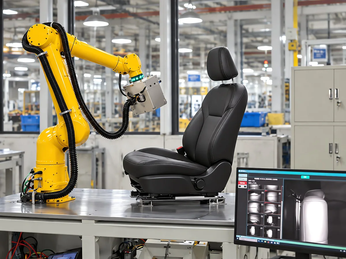
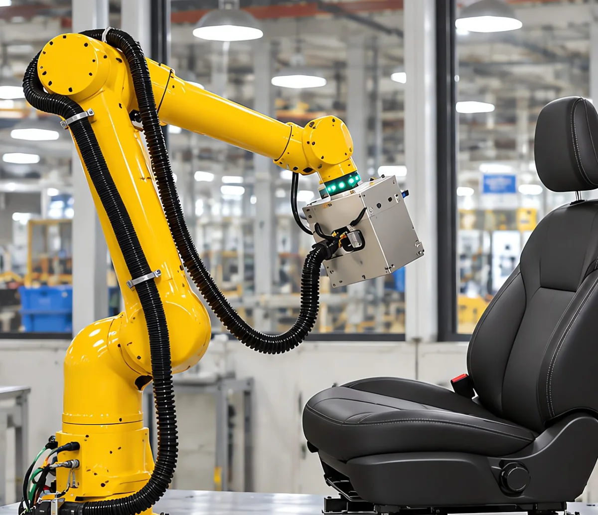
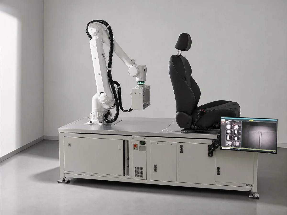
Equipment Configuration Reference
| Item | Configuration Notes |
|---|---|
| Inspection Objects | Wrapped three-dimensional parts (automotive seats, door panels, instrument panels, armrest console lids, center consoles, etc.) |
| Inspection Method | AI vision automatic inspection |
| image acquisition | Robot arm multi-angle on-the-fly capture |
| Images per part | More than 130 images (configured according to the inspection scope) |
| Single-image capture | About 200 ms |
| defect inspection | AI Deep Learning |
| Algorithm Foundation | CNN convolutional neural network |
| Result Output | OK / NG and Defect Position |
| Data Management | Image, result and report archiving |
| Computing Hardware | Industrial computer + discrete GPU |
| Software Technology | Host computer software + AI algorithm library |
| Model Update | Supports continuous training optimization |
Applicable Industry
Typical Industries These Solutions Are Installed In
Typical Applications combination
Solution combinations divided by part type and inspection purpose
Wrapped-part projects usually start with one item below or a combination of several, then expand according to the sample trial results. The table below lists the technical combinations common to this type of solution.
| Solution | Inspection Objects | Core Inspection Scope | Core Vision Technologies |
|---|---|---|---|
| Solution 1 | Automotive seat wrapped parts | Full-area surface acquisition of the cushion, backrest, headrest, side bolsters, and seam areas | Robot arm on-the-fly capture + multi-angle + AI |
| Solution 2 | Multi-curved areas of automotive seats | Plan shooting paths separately for areas of different curvature, material and texture | 3D path planning + multi-axis coordination |
| Solution 3 | Seats and door panels sharing one production line | Each product has its own product program, shooting path, image parameters, AI model and defect criteria | Recipe management + program switching |
| Solution 4 | Wrapped Door Panel Parts | Wrinkles, delamination, adhesive marks and contour fit in door panel trim, wrapped areas and decorative areas | Multi-angle + zoned imaging |
| Solution 5 | Armrest console lids and center console wrapped parts | Wrinkles, delamination, skipped stitches, stains, and scratches | Low-angle light + stitch inspection |
| Solution 6 | Instrument panel and pillar wrapped parts | Correct wrap seating on large curved surfaces, fully wrapped corners and splice misalignment | Zoned multi-station + morphology imaging |
| Solution 7 | Corner and edge finishing focus | Whether the four corners, bends and grooves are fully wrapped and free of exposed base | Dedicated corner views + contour analysis |
| Solution 8 | Stitching and splicing focus | Seam position offset, whether stitching runs straight, skipped stitch and thread breakage | Side light + sub-pixel measurement |
Implementation Workflow
Ten steps from project overview to delivery
A wrapped-part visual inspection system is not simply a matter of buying a camera and a robot arm; project implementation usually involves the following stages.
- 01 Product sample analysis: confirm workpiece dimensions, material, color, structure and surface condition
- 02 Defect standard confirmation: define what counts as OK and what counts as NG, and build a defect sample set
- 03 Inspection requirements confirmed item by item: inspection category, acceptance criteria and threshold
- 04 Vision testing and illumination trials: test camera, lens and light source imaging results for different areas
- 05 Robot path planning: plan the imaging trajectory according to the product's curved surface and the inspection zones
- 06 AI model training: build a defect recognition model using actual samples
- 07 Inspection zone division and acceptance criteria definition: edges, corners, and recesses are set as separate zones
- 08 Master sample baseline setup and parameter tuning
- 09 Complete machine integration and trial run: integrate the robotic arm, vision system, software platform and inspection logic, and measure over-rejection and escape
- 10 On-site validation and delivery: continuous running tests according to the actual production cycle time and quality standards, acceptance, training and operation and maintenance
Project Performance Validation Items
When the project is formally implemented, the following validation items are established according to the customer's specification, and the validation conclusions are subject to the samples and test conditions jointly confirmed by both parties.
| Validation Item | Validation Content |
|---|---|
| Imaging Accuracy | Pixel accuracy, field of view, defect visibility |
| inspection capability | OK / NG Sample Validation |
| Morphology Inspectability | Sample validation for wrinkles, blisters, and delamination |
| Repeatability | Multiple consecutive acquisitions |
| escape rate | NG Sample Validation |
| Over-rejection Rate | OK Sample Validation |
| CT | Complete inspection cycle per part |
| stability | Continuous operation test |
| data traceability | Linking images, results, and product information |
Why Choose EEK
Optics, algorithms, software and automation: all four layers delivered by the same team
Validate Illumination First, Then Discuss Algorithms
Most wrapped-part projects fail not because of the algorithm, but because morphological defects such as wrinkles and delamination never show up in the image at all. We make the imaging experiments thorough at the solution stage and only choose the algorithm route after confirming that the defects can be imaged.
Combine Technologies by Defect Characteristics Instead of Forcing a Single Solution
Where multi-angle 2D is sufficient, topography imaging is not layered on; stripe light or photometric stereo is introduced only when height variation has to be judged, and AI is added only when defects are hard to enumerate — the technical choice serves the inspection purpose and the cost.
No Fabricated Metrics, Sample Trial Results Prevail
Specifications such as accuracy, cycle time and escape rate are strongly tied to the workpiece and site conditions; we do not make numerical commitments that have not been measured, but run a sample trial first and then jointly confirm the achievable level.
Equipment and Automation Delivered as One Package
Optics, algorithms, software, robot arm paths and PLC integration are handled by the same team, avoiding the interface finger-pointing common when vision and production line belong to different suppliers.
This Category Solution
Other solution pages for the same type of problem
This type of solution is subdivided by inspection object and material. The table below lists the solution pages already built; the remaining sub-solution slots are reserved and will go live once the materials are complete.
This Category Document Checklist
Confirmed items and outstanding items
| Information Item | Description | Status |
|---|---|---|
| 3 existing wrapping application pages | Seat leather / door panel wrapping / armrest console lid and center console wrapping | Existing |
| 1 equipment product page available | Automotive seat AI visual inspection equipment (robotic arm on-the-fly capture + AI defect recognition) | Existing |
| Wrapping process flow chart | Describe each process step and key control point | To be added |
| Surface material and frame material | Determines illumination and topography imaging method | To be added |
| List of critical judgement positions | High-risk locations such as corners / turning points / grooves / seams | To be added |
| Wrinkle acceptance criteria | Which are acceptable and which must be NG must be defined jointly by the process and quality teams | To be added |
| Fixturing method and cycle time | Determines whether to use multiple cameras or sequential imaging | To be added |
| Traceability Requirements | Part numbers, batches, stations and process parameters that must be bound | To be added |
Common Question
Common Questions About This Type of Solution
What is the difference between wrapped-part inspection and general appearance inspection?
The biggest difference is that the defect source is the process rather than the material. Problems such as wrinkles, blistering and incomplete corner wrapping are deformations caused by the wrapping operation, and their shapes vary with hand movement, stretching and heating conditions, unlike scratches in the material itself, which are stable in shape. The solution therefore focuses on designing separate inspection areas and acceptance criteria for the key positions of the process, rather than applying one uniform standard to the whole part.
Can wrinkles be detected reliably?
It can be inspected, but the boundary of what is "acceptable" must be defined by the customer. The design styling itself has relief, and slight wrinkles permitted by the process also have room to exist, so the process and quality departments must first provide a grading standard, and reference samples must then be used to establish a reference baseline. Without a standard, no inspection result can be judged right or wrong.
Can delamination (unbonded areas) be detected?
It depends on how severe the delamination is. Obvious blistering produces measurable deformation and can be identified with fringe light or photometric stereo; but early delamination, where the face material separates slightly from the core and the surface has almost no deformation, has very weak visual features. The detectability of such items must be confirmed by measurement on real delaminated samples and cannot be promised.
Leather is highly reflective; will this affect imaging?
It does have an effect, but it can be handled. Genuine leather and PU leather become locally brighter, sometimes almost mirror-like, after pressure or stretching; this is usually suppressed with a polarizer together with diffuse light, or handled by switching to a morphology imaging method that is insensitive to highlights. Dark defects on dark materials have low contrast and also require dedicated illumination validation.
Why do wrapped-part inspections need a robotic arm? Can a fixed camera not do the job?
Wrapped parts are three-dimensional, and the inspection areas are distributed over curved surfaces facing several different directions. To cover every area with fixed cameras, you either install many of them or flip the workpiece through multiple orientations. A robotic arm can plan its path according to the workpiece's 3D structure and use a single acquisition unit to cover the areas of each orientation in turn; the shooting path can also be switched by part number, making it better suited to wrapped parts with many variants and large curved surfaces.
How many images can wrapped-part inspection equipment capture at one time?
The framework material for this type of solution gives a reference value of more than 130 images per part, used to cover different inspection areas. The actual number of images depends on the inspection scope, the way areas are divided and the minimum defect size requirement; it must be configured per project according to the workpiece and quality standard, and is not a fixed value.
How long does it take to inspect one wrapped part?
This type of solution uses fly capture, in which a single image can take about 200 ms to capture; the specific inspection cycle time is determined by the product structure, inspection area and imaging path. The complete-part cycle must also take loading and unloading and workpiece positioning time into account, and is subject to measured results from a sample trial.
How are corners and edges that are not fully wrapped (exposed substrate) inspected?
Corners are the highest-risk locations in the wrapping process and need separate inspection zones and dedicated viewing angles. The usual practice is to add camera angles at the four corners and the finished edges, use contour analysis to judge whether the facing material covers fully and whether the frame is exposed, and define the allowable degree in grades by position.
Can skipped stitches and broken threads be detected?
Yes. The contrast between the stitching and the background is usually low, so side lighting is needed to bring out the three-dimensionality of the stitch line, combined with contour and grayscale analysis to judge whether the seam runs straight and whether there are skipped stitches or broken threads. The specific acceptance criteria for stitching must be confirmed together with the quality department.
What can be done when dark defects on dark leather have low contrast?
Dark materials lower the brightness of both the defect and the background, and simply increasing gain does not improve the signal-to-noise ratio. The usual approach is to use low-angle light to highlight surface relief, use polarization to suppress highlights, or switch directly to a morphology imaging method that is insensitive to color, and to carry out dedicated illumination validation for that material.
Is it troublesome to change the vehicle model or part number?
Not difficult. The solution is managed by recipe: each part number corresponds to one set of capture paths, inspection regions, judgement parameters and thresholds, and switching is simply a matter of calling the recipe. Note that some morphology imaging requires re-acquiring baseline samples, so a changeover usually needs one trial run for confirmation rather than being a pure switch.
How Can Inspection Results Be Traced?
Inspection images, defect results, and OK/NG judgements are archived by product, time, and inspection result. Results can be bound to the part identifier, station, and batch, and where necessary can also be linked to wrapping process parameters. Archived NG images make later process improvement and traceback of batch problems easier.
What materials need to be provided for a wrapped part visual inspection solution?
Recommended to prepare: the physical product, product photos, 3D/CAD data of the product, product dimensions, material and color, inspection area, defect samples (OK samples and NG samples), the minimum defect size to be detected, production cycle time and daily output, the current manual inspection method, and whether inspection data traceability is required. The more complete the information, the easier it is to accurately plan the equipment structure, robot arm path, number of cameras, and AI inspection model.
What is the inspection accuracy?
[To be added] Wrapped parts are mainly judged for morphology and process defects, and "accuracy" here is more about how small a wrinkle or amount of deformation can be recognized; this depends on the imaging angle, the illumination method and the standard the customer permits, and must be measured with real parts.
Submit sample testing
Send us the workpiece, defect samples, inspection requirements and production line cycle time, and our solution engineer will determine which category of inspection problem it is and give recommendations on the imaging method and configuration.
Submitted successfully
We have received your sample testing request. A solution engineer will contact you within 1 business day via contact you.
Need to assess imaging conditions, defect criteria and cycle time item by item? Go to the Full Requirement Assessment →
Not Sure Which Category?
Send us the workpiece, defect samples and inspection requirements, and a solution engineer will determine which category of inspection problem it is and give recommendations on the imaging method, algorithm route and equipment configuration.