Connectors
For connector manufacturing and assembly, providing visual inspection solutions for pin presence/absence, terminal crimping, correct assembly seating and appearance anomalies.
Industry Production characteristics
How This Industry Produces Determines How Inspection Should Be Done
Visual inspection for connectors revolves around two things: first, making the most common defects in this industry image clearly and consistently, and second, integrating the judgement result reliably into the production line. The implementation constraints commonly seen in this industry are "small contact spacing makes adjacent contacts prone to sticking together" and "metal pins are highly reflective". Whether defects can be detected consistently depends on the material's optical properties, the minimum defect size and the cycle time, and is subject to the results of a measured sample trial.
Connector manufacturing is characterized by Small parts, high quantity, dense specifications. Products in the same series often differ only in a few contact positions and are easily confused visually.
Inspection priorities in this industry usually fall on "Every position filled, no position wrong": Verifying point by point by reference designator is more reliable than comparing the whole board and makes problems easier to locate.
Industry Inspection issues
Where problems actually occur on site
- Missing or bent pins
- Terminal crimping defect or missing terminal
- Plastic core not fully seated
- Housing clip not engaged
- Mixed material causing model mismatch
Typical Inspection Objects
The Most Common Inspection Objects in This Industry
Typical Inspection Task
The judgments to be made on these objects
- Pin presence/absence and deformation verification
- Terminal fully seated confirmation
- Plastic core and housing assembly check
- Model differentiation and mixed-material screening
- Packaging count verification
Vision Inspection Challenges
Implementation constraints specific to this industry
- Contact spacing is small, so adjacent contacts stick together easily
- Strong reflection from the metal pin body
- Plastic cores are similar in color (mostly black, white and gray)
- Precision parts place high demands on tooling positioning
Choosing the right algorithm
Choose by Acceptance Criteria Form, Not by How Advanced It Is
Position-by-Position Rule-Based Algorithm
Judge presence/absence and positional consistency by position number
Geometric Measurement
Measure pin body angle and position deviation to judge deformation
Classification
Distinguishing between models with similar specifications
acquisition and light source
Optical conditions set the upper limit of feasibility
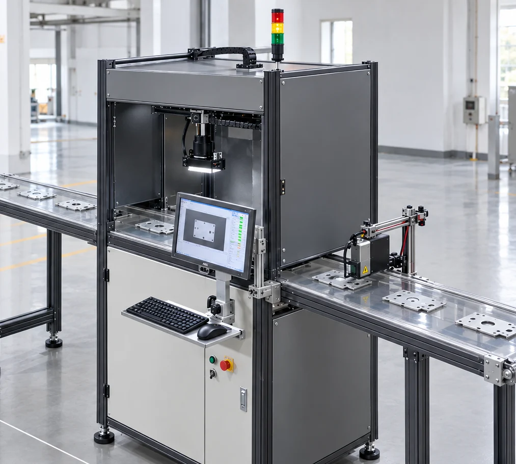
- Backlight or low-angle light makes fine pin contours clearer
- For metal pins, polarization is recommended to control reflections
- For black plastic cores with metal pins, avoid pin highlights masking the missing position
OK / NG Judgement
How results are judged and used
| Inspection Status | judgement | Interlocking Action |
|---|---|---|
| All contacts present, positions correct | OK | release |
| Missing pin / bent pin present | NG | Reject or divert to rework |
| Model Mismatch | NG | Treated as mixed material; the loading step must be checked |
PLC and Automation Interlocking
How results connect to the production line
We recommend outputting the defective Specific reference designators, making rework easier to locate.
If the production line has automatic cutting or packaging equipment, results can be wired directly to the rejection mechanism.
Applicable equipment
Common configuration forms for this type of inspection
Related Solutions
View the corresponding solution by inspection task
Common Question
The Questions Most Often Asked in This Industry
Can Connectors with Different Positions in the Same Series Be Distinguished?
Yes, mainly by counting contacts or by housing width features. If the two are identical in external dimensions and differ only in internal structure, a dedicated viewing angle is needed or another acceptance criterion must be used.
Can bent pins be detected?
Yes; this is a geometric measurement acceptance criterion and requires sufficient resolution and a stable datum. We recommend providing samples with known skew to verify the minimum angle that can be detected reliably.
For visual inspection in this industry, what needs to be solved first?
the implementation constraints commonly seen in this industry center on: "contact spacing is small and adjacent contacts stick together easily"; "metal pin bodies are highly reflective"; "plastic insulators are similar in color (mostly black, white or gray)". These constraints affect both the imaging solution and the cycle-time design, and normally a sample trial is needed to validate before the configuration is finalized.
How does the inspection result interlock with the production line?
We recommend outputting the specific position number of each defect, to make rework location easier. If the production line has automatic cutting or packaging equipment, the result can be wired directly to the rejection mechanism.
What Equipment Configuration Does This Type of Inspection Generally Require?
Common forms include: "EEK-SV5205C industrial vision presence/absence inspection equipment," "high-resolution precision part inspection station," "inline inspection system integrated with an automatic machine." The specific machine model and quantity depend on the inspection area, minimum defect size and line cycle time, and must be confirmed against site conditions.
Which process steps in this industry benefit most from a visual inspection station?
The most common is: "verification of pin presence/absence and deformation"; "confirmation that terminals are fully seated"; "checking the assembly of the rubber core and housing". Which process steps to actually instrument depends on the cost of defects escaping downstream and the cost of rework — the later a defect is found, the higher the cost.
How do we judge whether our product is suitable for visual inspection?
Please provide conforming connector samples together with samples with missing pins, bent pins, and mixed material, and state the contact pitch and minimum pin diameter. In general, as long as the acceptance criteria can be stated clearly, defects image clearly and consistently, and the cycle time matches the field of view, the project is feasible.
What inspection accuracy can be achieved?
Accuracy is not a fixed value that holds regardless of conditions. To be added — the minimum detectable size depends on the combination of field of view and camera resolution, and is also affected by illumination, lens and algorithm; the configuration must be derived from your minimum defect size and validated by measurement.
Submit sample testing
Please provide good connector samples and samples with missing pins, bent pins and mixed parts, and state the contact pitch and minimum pin diameter.
Submitted successfully
We have received your sample testing request. A solution engineer will contact you within 1 business day via contact you.
Need to assess imaging conditions, defect criteria and cycle time item by item? Go to the Full Requirement Assessment →
Inspection Configuration Based on Your Industry's Products and Cycle Time
Send us photos of the workpiece, the inspection requirement (what to inspect, and the tolerance for escapes and false calls), and the line cycle time, and our solution engineers will recommend the inspection method, optical solution, and interlocking configuration for that industry.