Screw Presence/Absence Inspection
Judges whether all required screws on a product are properly installed or missing, with single-screw or full-row verification, outputting OK/NG and interlocking with the production line for rejection.
inspection Overview
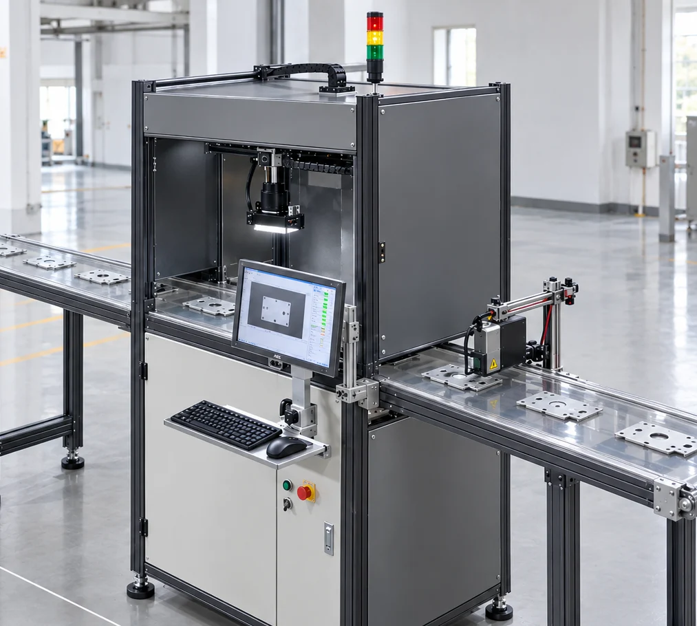
Screw presence/absence inspection: determine whether the screws that should be present on the product are installed correctly and whether any are missing; single screws or a whole row can be verified, outputting OK/NG and interlocking with production line rejection. The judgement usually does not check details such as threads or dimensions, but rather determines Whether the visual feature at that position exists and matches expectations, output OK / NG and interlock with the production line.
Verifies whether the screws that should be present on the product are fully seated or missing, with single-screw or full-row verification, outputting OK/NG and interlocking with production line rejection.
The feasibility of "screw presence/absence inspection" depends on Whether the visual features of the object are stable and distinguishable, as well as the on-site optical and tooling conditions. Each item is expanded below in the order commonly used in inspection engineering.
Object Characteristics
How the object appears in the image
- Small in size with many specifications, and multiple screw types are often mixed on one production line
- occupy few pixels in the image, making them sensitive to imaging resolution and focus
- Common forms are cross recess, hex socket, external hex, pan head and countersunk head
- After installation, usually only the head is exposed, so the acceptance criterion is mainly whether the head is present
inspection Challenges
Where Problems Really Occur on Site
- At low resolution, Phillips slots and hex sockets easily blur into a single bright spot
- Dark screws on dark workpieces have low contrast, making boundaries hard to segment
- Plated parts are highly reflective; specular reflection may drown out the head contour
- The same position may be a "screw hole", so a "hole" must be distinguished from a "hole with a screw installed"
Vision Judgement method
How acceptance criteria are set and why
The most stable acceptance criterion is Presence of the screw head: within the preset screw position area, judge whether a circular or hexagonal target matching the head features exists. Compared with judging threads or length, the head features are the easiest to extract stably from the image.
If "empty holes" interfere in the same area, you can further use Whether there is metallic highlight inside the hole or whether the head diameter is larger than the hole diameter to distinguish them. Such acceptance criteria must be confirmed on real captured images before use.
Applicable algorithm
Choose by the Form of the Acceptance Criteria, Not by Complexity
template matching
For screws at fixed positions with a single specification, standard head template matching is the most direct approach
Region Statistics
When positions are fixed but parts vary widely, presence is judged by regional brightness / texture statistics
Optical Precautions
Imaging conditions set the upper limit of feasibility
- Prefer Diffused light or ring light Reduce reflection from plated parts and keep mirror reflections from hitting the lens directly
- Can be attempted with dark screws Low-angle side light, using the specular contour at the head edge to make its presence stand out
- When screws are small, imaging resolution must be increased; if necessary, narrow the field of view and image in zones
- When verifying a full row of screws, note distortion and light falloff at the edge of the field of view, ensuring both sides use the same acceptance criteria
OK / NG Output
How results are judged and passed to the production line
| Inspection Status | judgement | Interlocking Action |
|---|---|---|
| All Screws in Place | OK | release |
| Any one missing | NG | Trigger the rejection or rework station |
| Cannot confirm (occlusion / reflection) | re-inspection | Re-capture or manual confirmation |
Applicable Industry
This type of inspection is common in the following industries
Common Question
The most common questions about this object
Are screw presence inspection and screw seating inspection the same thing?
Not exactly the same. Presence/absence inspection only judges whether the screw is there; in-position inspection must also judge whether it is tightened and to what depth. The criterion for the former is existence; the latter requires a measured quantity (such as the distance from the head to the datum surface). If both must be guaranteed, two criteria usually need to be layered at the same station.
Can Dark Screws on Dark Workpieces Be Inspected?
Yes, but illumination is needed to separate the head feature from the workpiece. The usual method is low-angle side light, which produces a distinguishable highlight or shadow at the edge of the screw head. The precondition is validation by actual imaging; experience alone is not enough.
Can a Whole Row of Screws Be Verified in One Pass?
Yes. The position of each screw is divided into an independent inspection region, judged region by region, and the results combined into the overall part result. Note that imaging quality at the edge of the field of view must be consistent with the central region.
What are the acceptance criteria for this object?
The most stable criterion is the presence of the screw head: within the preset screw position region, judge whether a circular or hexagonal target matching the head features is present. Compared with judging the thread or length, head features are the easiest to extract reliably from the image.
What are the illumination requirements for this type of object?
Prefer diffuse light or ring light to reduce reflection from plated parts and keep specular reflection from entering the lens directly. For dark screws, low-angle side light can be tried, using the bright contour at the head edge to make presence clear.
What Are the Inspection Accuracy and Minimum Detectable Size?
It depends on the combination of field of view and camera resolution, and is affected by the lens, illumination and algorithm. To be added — the configuration must be derived from your minimum defect size, subject to the results of a measured sample trial.
How Do We Verify That Our Product Can Be Detected?
Please provide real samples with screws installed and with screws missing (several of each), and our engineers will verify how distinguishable the head features are under those optical conditions.
Submit sample testing
Please provide real samples with screws installed and with screws missing (several of each), and our engineers will verify how distinguishable the head features are under those optical conditions.
Submitted successfully
We have received your sample testing request. A solution engineer will contact you within 1 business day via contact you.
Need to assess imaging conditions, defect criteria and cycle time item by item? Go to the Full Requirement Assessment →
Send Us Your Workpiece and We Will Show You the Measured Results
Provide several OK and NG samples, and the solution engineer will run actual imaging and judgement tests on the equipment, then give inspection configuration recommendations that can be implemented, rather than just reading a specification table.