Machine Vision Inspection for Curved and Free-Form Parts
Inspection of curved and free-form parts where the surface normal changes across the part: 2.5D photometric stereo, 3D and line-scan imaging combined with AI.
This Category positioning
Machine vision inspection of curved parts: 2D | 2.5D photometric stereo | 3D | line scan | AI vision | robot vision
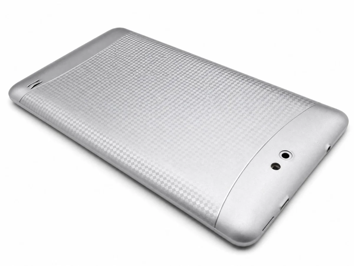
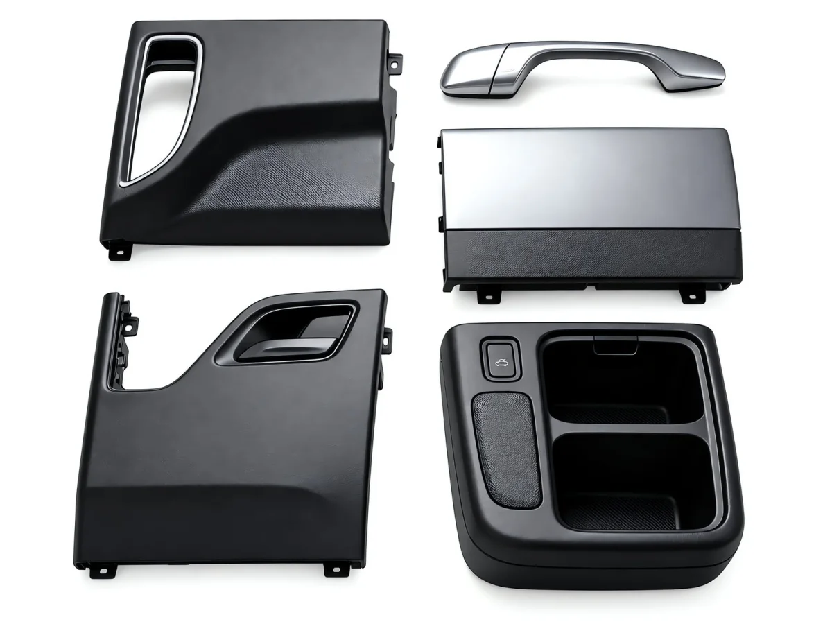
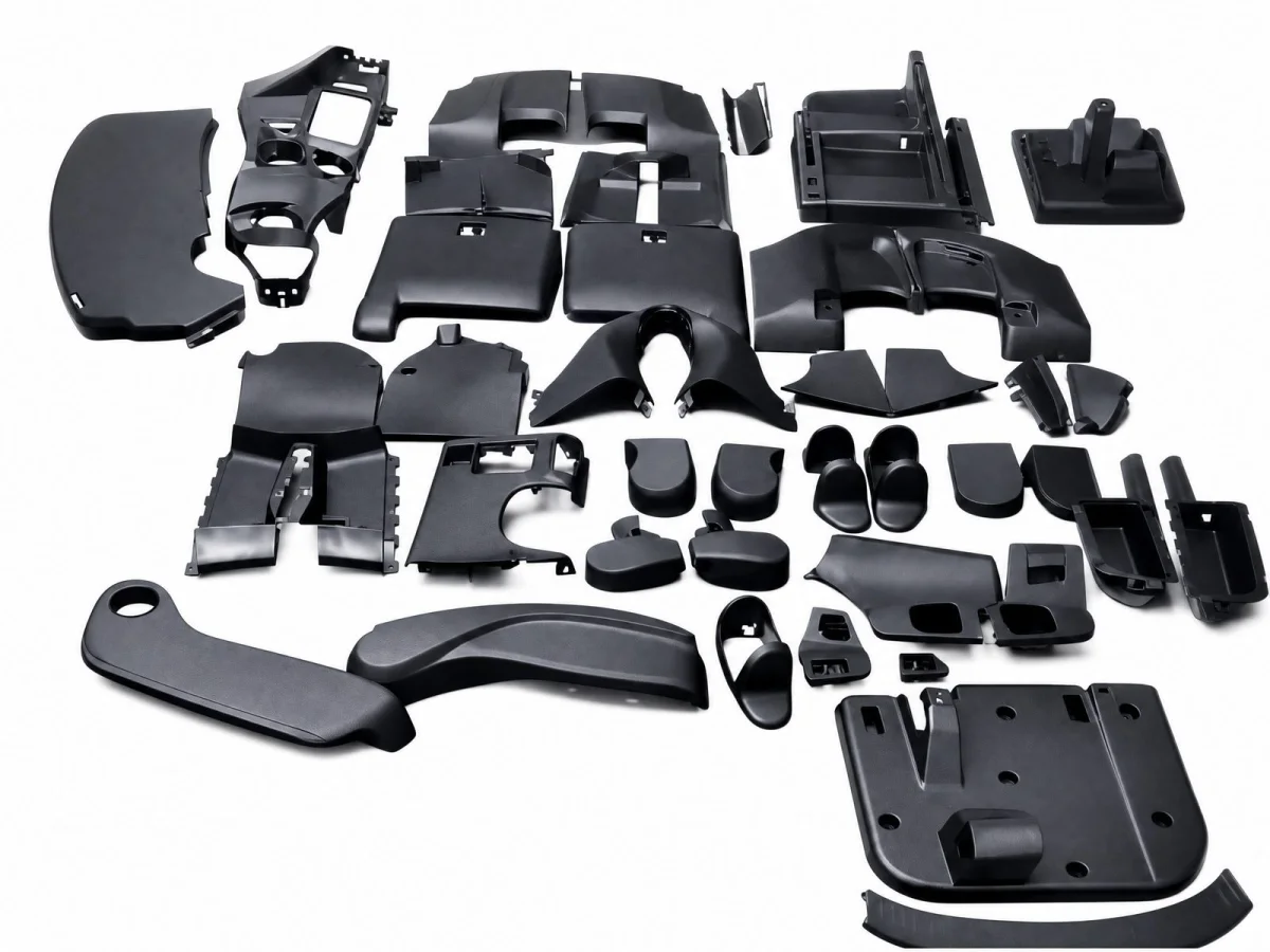
Curved-surface part visual inspection targets industrial products with curvature, curved faces, irregular faces and highly reflective faces, such as curved plastic parts, injection-molded housings, sheet metal parts, painted parts and automotive interior and exterior trim. What it has to solve It is not a question of "cannot be photographed", but of how to image stably, how to extract defect features, and how to keep the judgement consistent when material and curvature change. The engineering route is to combine 2D imaging, 2.5D photometric stereo, 3D measurement, line-scan imaging and AI algorithms according to the characteristics of the workpiece, rather than expecting a single camera and a single light source to cover every area.
The biggest difference between curved parts and flat parts is Surface normal direction differs at every point. For a flat part, as long as the camera and light source are relatively fixed, the imaging conditions are essentially uniform across the whole field; for a curved part, using the same illumination will inevitably produce "some areas overexposed and some areas completely black". The result is that defects in some areas are not revealed, and those that are revealed differ greatly in form — this is why, on a curved surface, "the same defect appears and disappears at different angles".
To address this, EEK's solution for curved-surface parts unfolds along three lines: first, Imaging Side, using multiple angles / multiple stations to cover areas facing different directions, or using a 2.5D photometric stereo multi-directional light sequence to reconstruct the surface topography, converting height-varying defects such as scratches, pits, bumps, and edges into a judgement-ready topography map; second, Algorithm Side, using AI segmentation and classification to handle complex defects whose forms vary and are hard to describe with fixed rules; third, Measurement Side, and through camera calibration and coordinate system establishment, measurement requirements such as dimensions, contour and position tolerance are placed on the same datum.
The complete chain of curved-surface part inspection can be summarized as six stages. After the product is loaded, optical imaging first produces multi-angle, multi-mode images, then the vision algorithm performs enhancement, registration and feature extraction, then the AI model performs defect recognition and classification, then OK / NG judgement is output according to rules, the judgement result drives the automation mechanism to complete sorting, and finally the inspection data and images enter the traceability system. If any link in this chain is missing, the inspection result stays at "it can be seen but not judged accurately".
- 01 Product loading and positioning
- 02 Optical imaging (2D / 2.5D / 3D / line-scan)
- 03 Image processing and feature extraction
- 04 AI defect recognition and classification
- 05 Rule-Based OK / NG Judgement
- 06 Automatic sorting and data traceability
Why Conventional Vision Difficult to inspect curved products consistently
The difficulty of curved-surface inspection is not "cannot capture it" but imaging stability, feature extractability and consistency of judgement
01 Complex Curvature
The product surface has several faces with different curvatures, and conventional single-angle vision tends to leave inspection blind spots — the imaging angle that suits one region may be completely unsuitable for another.
02 High Reflectivity
Metal parts, painted parts and high-gloss plastics easily produce strong reflections, and the signal from defects such as scratches and dents is easily drowned out by specular highlights, sharply reducing contrast.
03 Complex Materials
Different materials such as metal, plastics, painted surfaces and film require different optical imaging methods; if a single workpiece has both specular and matte areas, different illumination is often still needed zone by zone.
04 Small Defect Size
Defects such as fine scratches, pits, bumps and foreign matter are very small, so sufficient spatial resolution is required while at the same time ensuring that small defects still have usable contrast in the image.
05 Complex Appearance Standards
The same product may have several inspection requirements at once — color, surface, contour, dimension and assembly — and the acceptance criteria and thresholds differ from project to project, so one set of rules cannot be applied to them all.
06 Manual Inspection Is Inconsistent
Prolonged manual visual inspection is affected by fatigue, experience and ambient light, making it hard to maintain a unified judgement standard; contact measurement may also cause secondary damage.
One vision system, Covers different curved-surface inspection scenarios
According to workpiece material, curvature, defect types and production line cycle time, combines five technology routes: 2D / 2.5D / 3D / line scan / robot vision
Curved parts are not an industry, but a category Inspection technology scenarios. The five routes listed side by side on the same page correspond to five different classes of workpieces and requirements: 2D for routine appearance, 2.5D photometric stereo for tiny bumps and dents, 3D for depth and three-dimensional dimensions, line scan for continuous motion and large areas, and robotics for complex poses and multi-face inspection. Real projects are often a combination of two or three of them.
Solution 01 | 2D Visual Inspection
Industrial cameras and application-specific light sources acquire images of the product surface, suitable for conventional curved-surface appearance inspection. It suits products with a relatively simple structure and clear defect features.
- Appearance inspection · color inspection · contour inspection
- Dimensional inspection · presence/absence inspection · assembly inspection
- OCR character recognition · barcode / QR code recognition
Solution 02 | 2.5D Photometric Stereo Vision
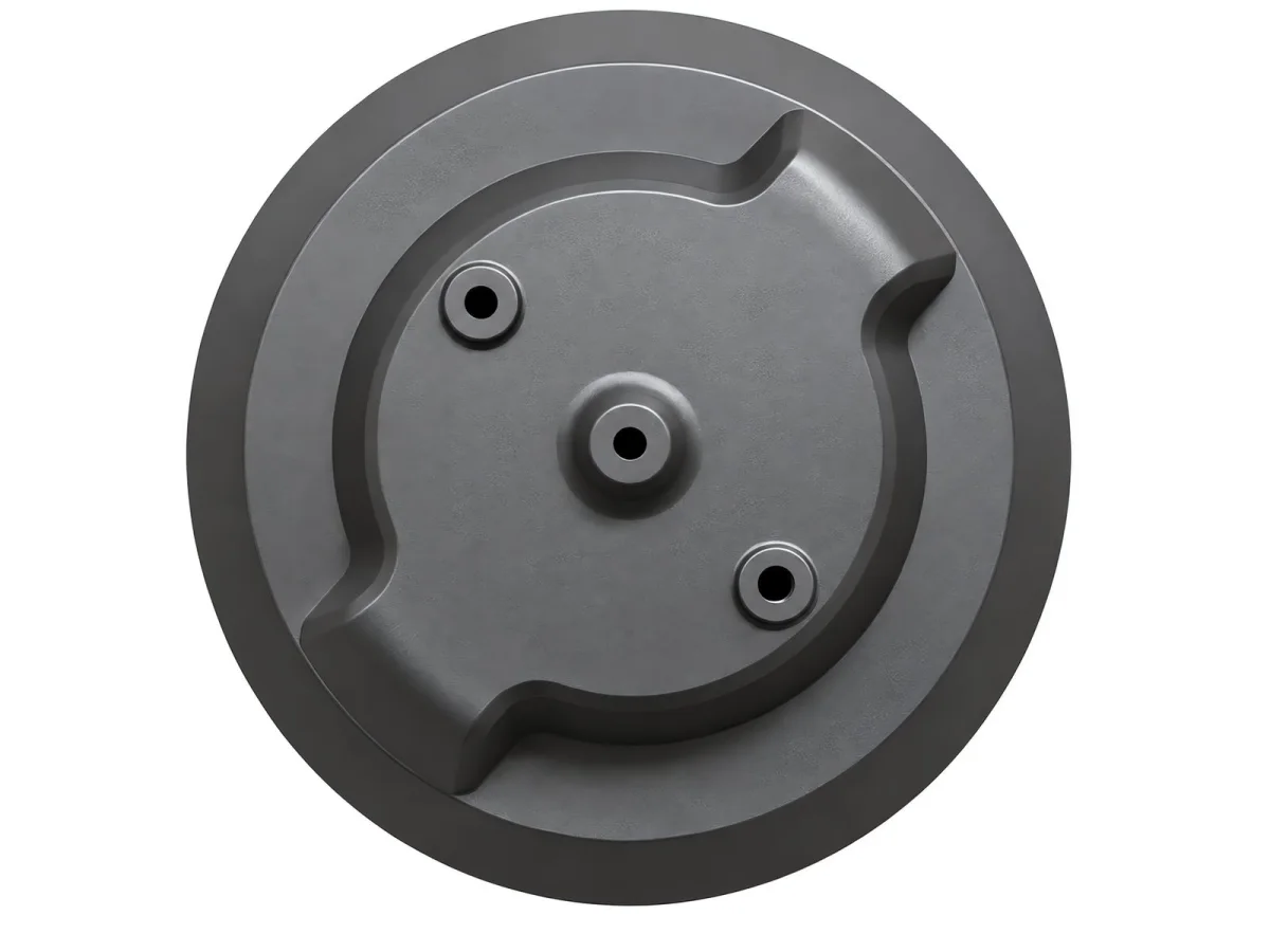
Multi-directional light sources image the product in successive passes, and a photometric stereo algorithm reconstructs the shape changes on curved surfaces that grayscale images cannot express, making small relief defects more obvious.
- Output: relative height map · normal vector map · curvature map · reflectance map · fused map
- Enhance defect features such as scratches · pits · bumps · edges · press marks · foreign matter
- The workpiece must stay still during imaging, usually combined with multi-index shots
Solution 03 | 3D Visual Inspection
Moving from 2D images to three-dimensional space inspection. For complex curved surfaces, depth changes and dimension-type inspection requirements, 3D vision technology is used to acquire three-dimensional product information.
- Height · depth · contour · flatness · curvature · volume
- Assembly height · 3D dimensions · position deviation
- Suited to complex structural parts, automotive parts, injection-molded parts and precision industrial products
Solution 04 | Line-Scan Visual Inspection
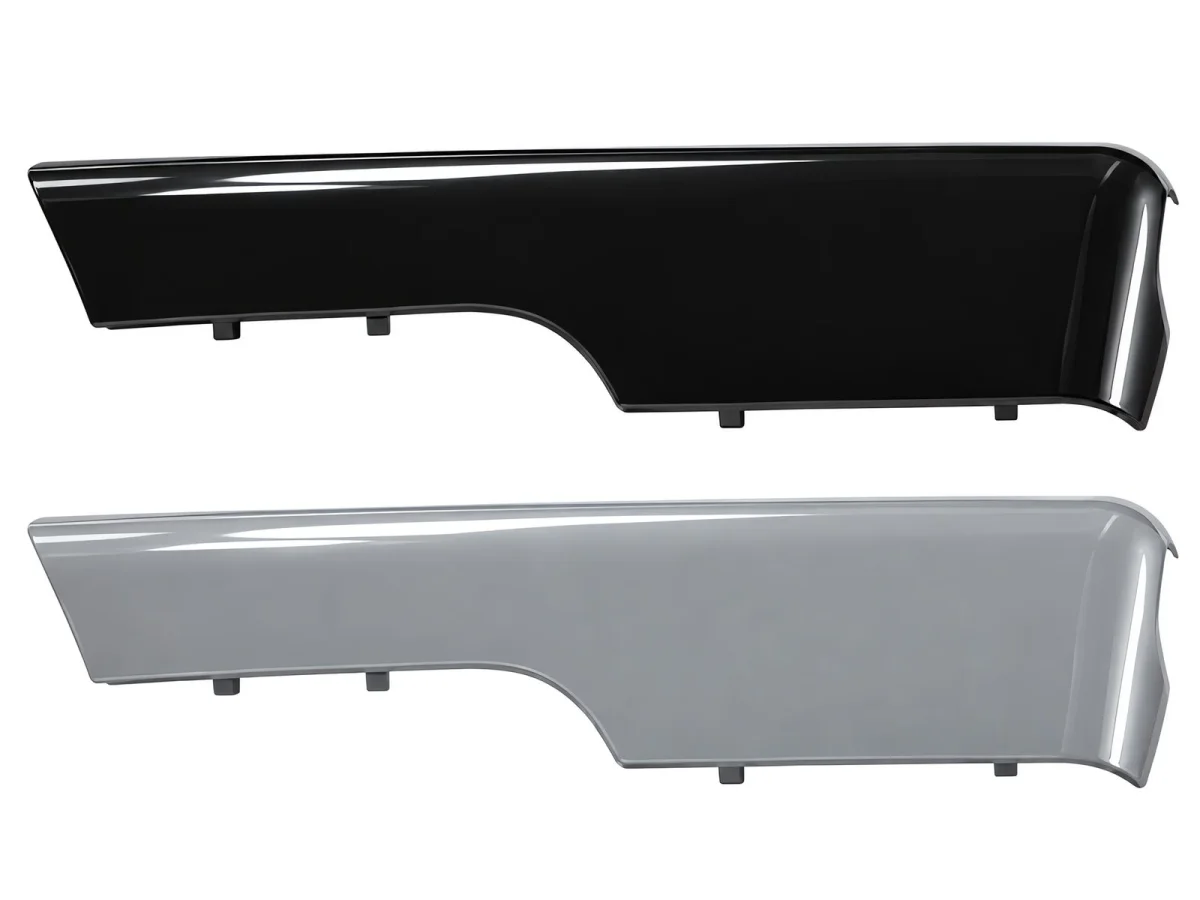
For continuously moving, large-format and unrollable curved products. A line-scan camera is combined with a high-speed motion platform, application-specific lighting and AI algorithms to achieve continuous scanning inspection.
- Applicable to metal sheets · sheet metal parts · coils · films · large plastic parts
- Applicable to cylindrical / curved products · glass · leather and other continuous-feed applications
- Inspection workflow: product motion → line scan acquisition → image stitching → defect recognition → NG rejection
Solution 05 | Robot Vision Inspection
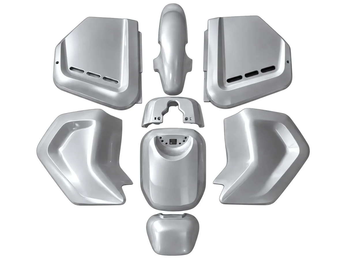
The mechanism rotates the product to enable multi-angle inspection. For applications where manual positioning is difficult, product pose is complex, or several faces must be inspected, robots / robotic arms, flexible fixtures, and AI algorithms carry out automatic picking, rotation, flipping, positioning, and multi-angle inspection.
- Multi-axis attitude adjustment: rotation + tilt, combined with camera or product movement to cover every orientation
- Flexible / contoured fixtures that support multi-model line sharing and quick changeover
- Suitable for automotive parts · injection molded parts · sheet metal parts · painted parts · home appliance structural parts
inspection Scope
What categories of problems does curved part inspection usually cover?
| Inspection Category | inspection item | Implementation Method |
|---|---|---|
| Appearance Defect | Scratches, scuffs, dirt, color difference, sink marks, flow marks | 2D multi-angle imaging + texture suppression |
| Morphology Abnormality | Dents, bulges, wrinkles, indentations, deformation | 2.5D photometric stereo / fringe light |
| Painting and Surface Treatment | Particles, sagging, orange peel, bare substrate, uneven coating | Diffused light + multi-angle imaging + AI classification |
| Edge and Contour | Profile, edge burr, flash, glue overflow, burr | Backlight or coaxial light for contour measurement |
| Dimension Measurement | Length, hole position, hole diameter, angle, positional tolerance | Calibration + feature point measurement |
| 3D Measurement | Height, depth, flatness, curvature, assembly height | 3D vision / point cloud processing |
| Assembly Features | Whether clips / bosses / ribs are complete, or missing or wrongly assembled | Zone inspection + template matching |
| Characters and Markings | Missing character, misprint, blur, barcode and QR code reading | OCR / Code Reading Algorithm |
| Pose and Orientation | Front/back, orientation, placement angle | Feature matching + pose solving |
inspection Object
Commonly inspected parts and materials, and the dedicated solutions already built
Typical defect
Which defects these solutions mainly target, and the inspection difficulty of each
| Defect Types | Typical Manifestations | Inspection Focus Points |
|---|---|---|
| Scratches and Scuffs | Linear damage on curved surfaces | Different orientations need different illumination; a single light source will inevitably miss defects |
| Dents and Protrusions | Local topography anomaly with height variation | 2.5D photometric stereo / fringe light is most reliable |
| wrinkle | Buildup caused by wrapping or forming | Whether a wrinkle is acceptable requires the customer to define clear criteria |
| indentation | Caused by force or stacking | Distinguish these from design styling to avoid judging styling as defects |
| Sink marks and flow marks | Uneven surface gloss on injection molded parts | Consistent imaging requires stable multi-angle illumination |
| Burrs and Flash | Flash at the parting surface, excess material at edges | Backlight or coaxial light for contour measurement |
| Burrs | Small protrusions left at edges and hole positions | Requires contour imaging + high-speed algorithms to avoid edge interference |
| crack | Surface cracks and abnormal texture | Low contrast and unpredictable direction usually require AI segmentation |
| Dirt and Foreign Matter | Surface contamination, attached foreign matter | Take care to distinguish these from the material's own texture and spots |
| color difference | Chromaticity deviation within or between parts | Curved reflective surfaces affect chromaticity measurement and require dedicated handling and fixed lighting |
| Coating Defects | Particles, sagging, orange peel, bare substrate, uneven coating | Painted parts have both specular and diffuse reflection, requiring zone-based illumination |
| Welding Defects | Weld spot anomalies, weld spatter and cracks on sheet metal weldments | Requires 3D height information for judgement |
| Short Shot and Shrinkage Void | Local short filling on injection molded parts | Often superimposed on curvature changes, so zone-specific criteria are required |
| Hole position and structural anomalies | Hole offset, hole blockage and out-of-tolerance position | Measure against the drawing datum after calibration |
| Missing assembly parts and misalignment | Missing part, wrong part, position offset, reversed part | Zone-based inspection + template matching + pose estimation |
From "Surface Appearance"to "reading defects"
Nine core capabilities of visual inspection for curved parts
Surface Scratches
Detects fine linear scratches on product surfaces. Scratches on curved surfaces run in different directions, so multi-angle imaging is needed to cover them all and avoid escape in any single orientation.
Pits / Bumps
Detects 2.5D surface height changes. These defects have low gray-level contrast and only become reliably judgeable after enhancement with relative height maps and fused images.
Discoloration
Detects color anomalies and local color difference. Reflections on curved surfaces interfere with colorimetric measurement, so fixed illumination conditions and dedicated color processing are required.
Dirt / Foreign Matter
Identifies surface contamination and attached foreign matter on the product and distinguishes them from the material's own texture and color spots, avoiding judging texture as a defect.
Burrs
Detects burrs at edges and hole positions. Contour imaging plus algorithms are needed to suppress the interference signal of the edge line itself.
crack
Identifies surface cracks and abnormal texture on the product. Contrast is low and orientation is variable, so AI segmentation is usually used to extract the region before classification.
Coating Defects
Detects anomalies such as uneven coating, sagging, particles, orange peel and bare substrate. Painted parts combine specular and diffuse reflection, requiring zoned illumination and AI classification.
Dimension / Contour
Performs product dimension, contour and position inspection. Calibration and drawing datum are prerequisites, and fixturing repeatability is usually the dominant error source.
Assembly Inspection
Inspect for missing parts, wrong parts, position offset and other issues. Set acceptance criteria per region, combined with template matching and pose solving.
AI vision: Complex defects are easier to identify
For complex defects that are difficult to describe with fixed rules, AI algorithms perform segmentation, extraction, classification and judgement
Traditional rule-based vision relies on manually defined thresholds and features, and often struggles to describe defects reliably when their shapes vary, their boundaries are blurred, or they behave inconsistently on different materials. Scratches, discoloration, dirt, coating defects and complex textures on curved parts fall into this category. In such scenarios EEK adopts AI inspection, AI segmentation, AI classification, anomaly detection, OCR, object localization and other algorithm capabilities, turning defect recognition from "writing rules" into "learning features".
In engineering terms, a complete algorithm chain has been formed: the raw image first undergoes AI segmentation to obtain defect regions, then bounding regions are extracted from the segmentation results and defects are aggregated; the defects then enter an AI classification model by defect type, and finally pixel-level geometric results (length, width, area, coordinate center, defect box) are calculated and passed to the rule judgement stage to output OK / NG. This chain separates "does it look like a defect" and "does it count as out of tolerance" into two steps, and the basis for judgement is traceable.
- 01 Image Input
- 02 AI Defect Segmentation
- 03 Defect region extraction
- 04 Defect aggregation and image cropping
- 05 AI Defect Classification
- 06 Pixel-level result computation
- 07 Rule-Based Judgement
- 08 OK / NG Output
AI Inspection and Positioning
Locates the target and defect positions in the image to provide regions of interest for subsequent segmentation and judgement, reducing interference from irrelevant areas.
AI Segmentation
Performs pixel-level region partitioning to separate defects, workpiece areas and background. Especially effective for defects with blurred boundaries and irregular shapes.
AI Classification
Judge the type of each segmented defect region (for example scratch / bump / white spot), with support for setting acceptance criteria separately by defect type.
Anomaly Detection
For scenarios with few samples and defect shapes that cannot be exhaustively listed, the model is built from normal samples, and regions that deviate from the normal form are flagged as anomalies.
OCR Character Recognition
Recognizes characters, batch numbers and markings on the product surface, judges missing, misprinted and blurred ones, and can be linked to production data for traceability.
Target Positioning and Measurement
Extract the geometric quantities of the defect region (length, width, area, centroid coordinates) and output defect boxes for rule-based judgement and result retention.
Industrial Vision Inspection Software Platform
Unifies algorithms, cameras, motion control, IO, recipes, users, logs and data in one visual inspection system
Curved-surface part inspection projects often involve multiple imaging setups, multiple defect criteria and switching between several models at the same time. If these are scattered across different small programs and configuration files, model changeover, parameter tuning and traceability later all become a burden. The EEK visual inspection software platform converges the capabilities needed for inspection into a single system: algorithms and camera parameters, motion axes and IO points, product recipes and batches, user permissions and run logs, inspection images and result data are all managed in one interface.
Recipe Management
Supports vision inspection recipe management for different products, models and batches. Call up the corresponding recipe when changing models to avoid re-tuning parameters item by item.
Algorithm Communication
Quickly combines vision inspection algorithms through a visual workflow, building inspection flows like stacking blocks to reduce repeated coding.
Motion Control Module
Supports motion axes, IO and equipment control, enabling vision and motion coordination within the same system and reducing additional control hardware.
Data Management
Records OK / NG results, inspection time, batch and inspection images, providing raw data for quality analysis and process optimization.
Log Management
Supports operation logs, operation audit and system maintenance records to meet management requirements for traceable processes and accountable responsibilities.
data traceability
Supports production data queries, report output and product failure analysis, tracing inspection results back to the specific batch and workpiece.
From Optical Imaging through to a complete automatic sorting chain
Six-layer technical architecture of visual inspection for curved parts
- 01 Optical Imaging
- 02 image processing
- 03 AI algorithm
- 04 Visual Judgement
- 05 Automated execution
- 06 data traceability
01 Optical Imaging
Determines whether defects can be seen
- Industrial camera / line-scan camera
- 2D light source, multi-angle illumination
- 2.5D photometric stereo light source
- 3D vision sensor
02 Image Processing
Turn raw images into usable information
- Image enhancement and correction
- Relative height map / normal vector map
- Curvature map / reflectance map
- Multi-channel image fusion
03 AI Algorithm
Handles defects that are hard to describe with rules
- AI detection · AI segmentation · AI classification
- Anomaly Detection
- OCR · Object Positioning
- Pixel-level result computation
04 Visual Judgement
Turn algorithm results into acceptance criteria
- OK / NG judgement
- Defect classification and grading
- Dimension and tolerance judgement
- Rule-based judgement and threshold management
05 Automated Execution
Turn judgement results into production line actions
- Robot / robotic arm picking and sorting
- Motion platform and multi-axis pose adjustment
- Rejection Mechanism
- OK / NG sorting belt conveyor
06 Data Traceability
Make inspection results searchable and traceable
- Production data and inspection images
- NG logging and batch management
- Quality analysis and reports
- PLC / MES Integration
inspection Method
Combined Route of Imaging, Algorithm and Judgement
Multi-angle Imaging
Give every zone an appropriate view
- Multiple cameras / stations cover regions facing different directions
- Or a single camera with a turntable / flipping mechanism imaging in stages
- The key is coverage, not simply adding more cameras
Photometric Stereo
Convert three-dimensional topography into an image that can be judged
- Multi-directional light sequences reconstruct surface normals and curvature
- Most effective for defects such as dents, wrinkles and indentations
- Requires the object to remain stationary during imaging
Calibration and Measurement
Dimensional items rely on calibration, not on guessing pixels
- First perform camera calibration and establish the coordinate system
- Define the measurement datum from the drawing datum
- Fixture repeatability is usually the dominant error source
Algorithm and Judgement
Zone judgement + overall conclusion
- Apply different acceptance criteria by area
- AI segmentation handles defects with varied shapes
- Boundary cases are defined by the customer's quality standard
inspection workflow
- 01 Confirmation of the part 3D structure and key inspection surfaces
- 02 Imaging solution design (angle coverage + illumination method)
- 03 Confirm the fixturing and positioning solution
- 04 Camera calibration and coordinate system setup
- 05 Multi-angle / multi-pose image acquisition
- 06 Morphology reconstruction and defect segmentation
- 07 Dimension measurement and assembly feature verification
- 08 Overall judgement OK / NG and output
Curved-surface visual inspection, Covers multiple manufacturing industries
Inspection Objects and Key Inspection Items by Industry
automotive parts
Automotive interior and exterior trim, injection molded parts, metal stamped parts, aluminum alloy parts, coated parts, structural parts, wheels and trim
Sheet Metal and Stamping
Stamped parts, sheet metal housings, metal panels, hardware, drawn parts, bent parts, welded parts
injection molding
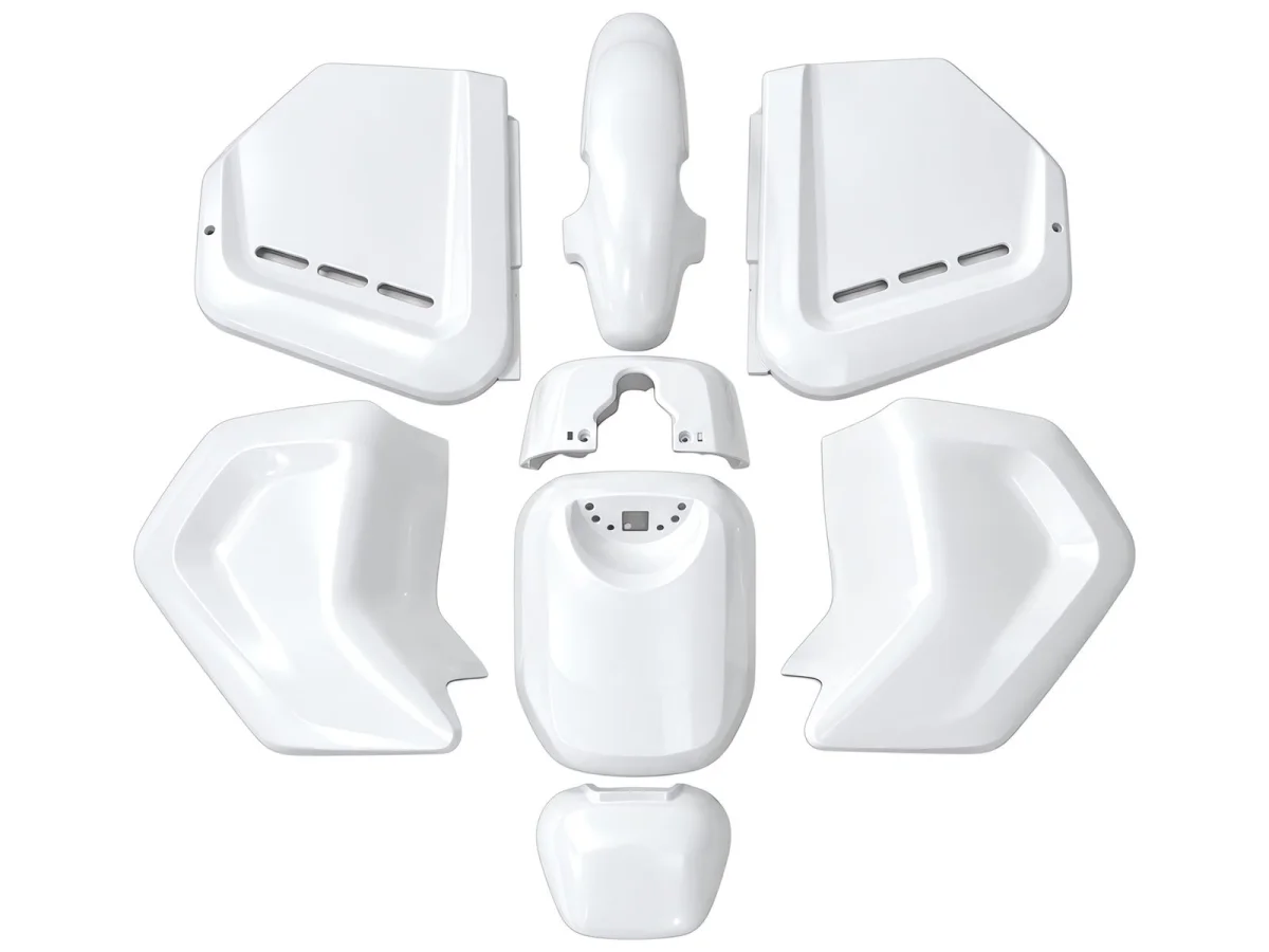
Injection-molded housings, plastic parts, precision injection-molded parts, home appliance plastic parts, 3C plastic parts and automotive plastic parts
Painting and Surface Treatment
Painted parts, powder-coated parts, baked enamel parts, automotive and home appliance painted parts, metal painted parts
3C electronics
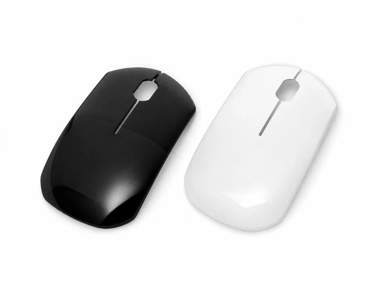
Phone structural parts, computer housings, mice, keyboards, headphones, and consumer electronics housings
home appliance
Home appliance housings, plastic parts, metal panels, painted parts, decorative parts
Precision Manufacturing
Precision metal parts, precision plastic parts, machined parts, structural parts
Lithium Battery and New Energy
Multi-station appearance inspection scenarios such as battery cell appearance, electrode sheets, insulating parts and structural parts
Die Casting and Castings
Die-cast housings, casting surfaces, edges and contours after deburring, and machined surface quality
Typical Visual inspection case
Three representative scenarios grouped by technical approach
Case 01 | Prismatic Lithium Battery Cell Appearance Inspection
Multi-station 2.5D / 3D + AI visual inspection. Vision modules are designed separately for each surface material, and deep learning networks are configured according to the strengths of each imaging method, covering the large face, bottom face, narrow side face, top face and terminal post areas.
- Inspection scope: multiple defect types such as explosion-proof valves, PP film, terminal posts, aluminum shells and blue film
- Per the project documentation: the inspection item covers 78 defects, managed by grade as CR (critical) 6 / MA (major) 33 / MI (minor) 28
Page tags: AI vision | 2.5D | 3D | multi-station | lithium battery
Case 02 | Complex Curved Surface Appearance Defect Inspection
Photometric stereo visual inspection. It images in successive passes under multi-directional illumination and combines a height map, a reflectance map, and AI algorithms to enhance minute defects on the product surface, restoring topography changes that are hard to resolve in grayscale into a judgement-ready image.
- Typical inspection: dent | bump | scratch | foreign matter | edge defect
- Applications: high-gloss plastic parts, curved housings and workpieces where tiny bumps and pits must be resolved
Page tags: photometric stereo | 2.5D | height map | AI segmentation
Case 03 | Mouse / Consumer Electronics Appearance Inspection
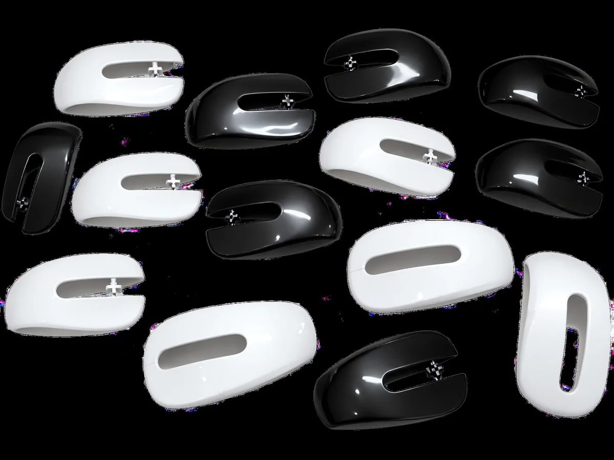
AI inspection of consumer electronics curved surfaces. Through multi-angle vision imaging and AI defect recognition, it automatically inspects appearance defects on high-gloss curved housings; the workpiece pose is adjusted by a multi-axis mechanism so that the cameras achieve multi-angle coverage.
- Inspection scope: scratch | bump | white spot | discoloration | dirt | edge defect
- Typical configuration: multi-angle imaging + photometric stereo + AI classification + automatic sorting
Page tags: AI Vision | Multi-angle Imaging | Robot / Multi-axis | 3C Electronics
From Sample Testing to mass production deployment
Six-step implementation process: requirement analysis → sample testing → solution design → algorithm development → equipment integration → on-site delivery
- 01 Requirement Analysis
- 02 sample testing
- 03 solution design
- 04 Algorithm Development
- 05 Equipment Integration
- 06 On-Site Delivery
STEP 01 Requirement Analysis
Understand the product, defect types, inspection accuracy requirements, and line cycle time, and define which items must be detected automatically and which items can be covered manually as a fallback.
STEP 02 Sample Testing
Validates imaging on real samples with different cameras, lenses and light sources to first confirm whether a workable imaging solution exists for the defect.
STEP 03 Solution Design
Determine the technical route — 2D / 2.5D / 3D / line scan / AI — together with the number of cameras, imaging angles, fixturing and cycle time.
STEP 04 Algorithm Development
Build the inspection model, rules and defect classification standards, train and validate them with real samples, and fix the acceptance criteria in the recipe.
STEP 05 Equipment Integration
Completes the integration of vision, mechanics, electrical systems, robots and software, and jointly commissions the production line cycle time and loading and unloading interface.
STEP 06 On-Site Delivery
Completes on-site debugging, validation, training and mass production introduction, and confirms inspection capability item by item against the acceptance criteria.
Why Choose EEK
Describe with concrete capabilities, not adjectives
Optical Capability
2D, 2.5D photometric stereo, 3D, line scan, and multi-light imaging. The imaging method is selected according to workpiece material and curvature, rather than using one lighting setup for every surface.
AI Algorithm Capability
Covers AI detection, segmentation, classification, anomaly detection and OCR, turning complex defects that are hard to describe with fixed rules into judgeable results.
Automation Capability
Motion platforms, robots, manipulators and automatic sorting. Inspection results drive production line actions directly rather than only producing a report.
Software Capability
Vision inspection software platform that uniformly manages recipes, algorithm flows, motion control, logs and data, and supports changeover and traceability.
Project Capability
Integrated project implementation from sample testing to equipment delivery, covering requirement analysis, imaging validation, algorithm development, integration, and on-site delivery.
Industry Capability
Covers inspection scenarios in the automotive, 3C, sheet metal stamping, injection molding, coating, home appliance, lithium battery and precision manufacturing industries.
This Category Solution
Dedicated solution pages broken down by part type, plus reserved solution slots
This type of solution is subdivided by inspection object and material. The table below lists the solution pages already built; the remaining sub-solution slots are reserved and will go live once the materials are complete.
This Category Document Checklist
Confirmed content and items that require business information before they can be finalized
| Information Item | Description | Status |
|---|---|---|
| Solution Pages in This Category | Dedicated solution pages broken down by part type (currently a placeholder) | To be added |
| Part 3D drawing and key inspection surfaces | Determines the imaging angle coverage plan | To be added |
| Minimum radius of curvature of the curved surface | Excessive curvature reduces the effective imaging area | To be added |
| Material and surface reflection characteristics | Mirror / matte finish determines the illumination method | To be added |
| Appearance acceptance criteria | Which topographies are acceptable must be specified by the customer | To be added |
| Dimension items, tolerances, and datum definition | Establish the measurement coordinate system from the drawing datum | To be added |
| Fixturing method and repeat positioning accuracy | Main error sources in dimensional measurement | To be added |
| Target cycle time and allowed number of stations | Determines whether to use multiple cameras or sequential imaging | To be added |
| Defect samples (several OK / NG each) | Determines whether the algorithm approach can be validated | To be added |
| Production line integration requirements | PLC brand, communication method, loading and unloading method and site space | To be added |
Common Question
Common Questions About Visual Inspection of Curved Parts (click to expand)
What is visual inspection of curved parts?
Curved-part visual inspection uses machine vision, 2.5D photometric stereo, 3D, line scan and AI algorithms to inspect the appearance, dimensions, defects and assembly state of industrial products with curvature, arc surfaces or irregular structures. Its fundamental difference from flat-part inspection lies in Surface normal direction differs at every point, so the imaging solution must be designed around "multi-angle coverage" rather than using one fixed light source for everything.
Why Do Curved Products Need 2.5D Vision?
For scratches, pits, bumps and edges such as these Has height variation defects may be hard to express reliably with two-dimensional grayscale information alone. Photometric stereo uses multi-directional illumination to obtain information such as relative surface height and normal vectors, thereby enhancing 2.5D surface defect features. Dents and bumps in particular often appear in a conventional grayscale image as only a slight light-dark variation, whereas they clearly take shape in the height map and the fused image.
Can curved parts be inspected with a line-scan camera?
Yes. For products that move continuously, are large, are web materials, have cylindrical surfaces, or need to be inspected in an unrolled state, line-scan cameras combined with a motion platform and professional light sources can scan continuously. The advantage of line scan is area coverage and continuous material travel, but it requires Stable relative motion between the product and the camera, so it is better suited to inline production line scenarios rather than static sampling at a station.
Are curved parts suitable for AI visual inspection?
Suitable. For scratches, discoloration, dirt, coating defects, complex textures and similar Difficult to describe with fixed rules defects, AI detection, AI segmentation, AI classification, or anomaly detection algorithms can be used. It should be noted that the effectiveness of AI algorithms depends heavily on sample quality — the quantity and coverage of defect samples affect the final result more directly than the model architecture does.
Can Injection-Molded Parts Be Visually Inspected?
Yes. For injection-molded parts, a visual inspection solution can be designed to address flash, burrs, sink marks, short shots, bubbles, black spots, white spots, off-color, scratches and deformation. What makes injection-molded parts special is that Sink marks and flow marks are gloss unevenness, requiring stable multi-angle illumination for consistent imaging; otherwise the same part imaged at different stations will give inconsistent results.
Which Defects Can Be Detected on Sheet Metal Parts?
Scratches, dents, burrs, deformation, off-color, welding anomalies and other surface defects can be inspected according to the product's actual requirements. The difficulty with sheet metal parts often lies in Large area and complex edges — There must be enough spatial resolution to cover the whole part, while also handling interference signals from bent edges and hole edges.
Can Painted Parts Undergo AI Visual Inspection?
Yes. The color, surface texture and appearance defects of painted parts can be inspected by combining application-specific optical imaging with AI vision algorithms. The difficulty with painted parts is Specular and diffuse reflection coexist: particles and orange peel are texture-type anomalies, sagging and strike-through are large-area topography anomalies, and scratches depend on directional illumination, so different illumination is often used by zone and different defects are modeled separately.
Why are curved parts harder to inspect than flat parts?
because Surface normal direction differs at every point. Flat parts can achieve consistent imaging conditions with one fixed illumination setup, whereas with the same lighting a curved part will have some areas overexposed and others underexposed, and defects appear differently in different areas. The way forward is to increase imaging angle coverage, or switch to photometric stereo reconstruction of topography, which is insensitive to the viewing angle.
Can all scratches on curved surfaces be detected?
Cannot be generalized; it depends on Scratch orientation and curvature. Directional illumination lights scratches in one orientation very well while reducing the contrast of scratches in another orientation, so multi-directional illumination or even multi-angle imaging is needed for coverage. For areas with strong curvature or near-mirror surfaces, detectability must be confirmed by measurement; you cannot draw conclusions from camera resolution alone.
Can dimensional inspection be done at the same time on curved surfaces?
Yes, but first you need to Accurate Coordinate System Setup. The dimensions of a curved part are usually referenced to the drawing datum, so the camera must be calibrated first and a measurement coordinate system established from the datum. The larger error source is often fixturing repeatability — if the clamping position deviates every time, even higher resolution will not measure accurately. This point needs to be settled together with the process at the solution stage.
What is the inspection accuracy?
The inspectability of appearance items and the measurement accuracy of dimension items are two different things: appearance depends on defect contrast and imaging angle coverage, while dimensions depend on calibration accuracy, fixturing repeatability, and the algorithm's measurement method. Both Must be confirmed by measuring real parts so a single isolated accuracy figure cannot represent the whole solution.
How many cameras are needed?
It depends on Number of areas and orientations to be covered, as well as the cycle time requirements. If a turntable or flipping with separate imaging passes can meet the cycle time, fewer cameras are needed; if the cycle time is tight and multiple passes are not allowed, several cameras must image simultaneously. This must be evaluated against the part drawing and the line cycle time — more cameras is not necessarily better.
Are the solutions the same for matte and mirror-finish materials?
No, they are different. Matte surfaces are suited to diffuse light for inspecting flaws, while mirror-finish high-gloss parts need coaxial light, polarization or a multi-angle combination to suppress specular reflection, otherwise the image is drowned by highlights. If the same part has both mirror and matte areas, it often requires Different illumination in each zone.
Further Reading
Submit sample testing
Send us the workpiece, defect samples, inspection requirements and production line cycle time, and our solution engineer will determine which category of inspection problem it is and give recommendations on the imaging method and configuration.
Submitted successfully
We have received your sample testing request. A solution engineer will contact you within 1 business day via contact you.
Need to assess imaging conditions, defect criteria and cycle time item by item? Go to the Full Requirement Assessment →
Not Sure Which Category?
Send us the workpiece, defect samples and inspection requirements, and a solution engineer will determine which category of inspection problem it is and give recommendations on the imaging method, algorithm route and equipment configuration.