3C Electronics
For the precision assembly stages of phones, wearables, computers and consumer electronics, providing inspection solutions for tiny part presence/absence, correct assembly seating and appearance.
Industry Production characteristics
How This Industry Produces Determines How Inspection Should Be Done
The visual inspection of 3C electronics revolves around two things: first, making the most common defects in this industry image clearly and consistently; second, connecting the judgement result reliably into the production line. Common implementation constraints in this industry are "parts are extremely small, placing high demands on resolution and focus"; "assembly space is tight, making the viewing angle difficult to arrange". Whether detection can be stable depends on material optical properties, minimum defect size, and cycle time, and is subject to the results of a measured sample trial.
The characteristics of 3C electronics are Extremely small parts, extremely dense assembly, extremely high appearance requirements. A 1 mm screw or a 0.3 mm clip is key to the function and feel of the complete machine.
At the same time, model changeover in this industry is fast, The inspection solution must switch quickly with the product, which means recipe management and changeover efficiency matter no less than inspection accuracy itself.
Industry Inspection issues
Where problems actually occur on site
- Missing tiny parts (screws, clips, foam)
- Flat cable / FPC not fully inserted
- Missing shields and insulation parts
- Appearance scratches, dirt, press marks
- Labels and serial numbers must be checked one by one
Typical Inspection Objects
The Most Common Inspection Objects in This Industry
Typical Inspection Task
The judgments to be made on these objects
- Checking for missing micro screws and clips
- Connector and FPC mating confirmation
- Appearance anomaly identification
- Serial number reading and verification
- Attachment and packaging content verification
Vision Inspection Challenges
Implementation constraints specific to this industry
- Parts are extremely small, placing high demands on resolution and focus
- Assembly space is tight, making the viewing angle hard to arrange
- High-gloss surfaces (glass, mirror-finish metal) reflect strongly
- Frequent changeovers mean recipes must switch fast and without errors
Choosing the right algorithm
Choose by Acceptance Criteria Form, Not by How Advanced It Is
High-Resolution Rule-Based Algorithm
Micro parts use high-resolution imaging + template / region judgement
Anomaly Detection
Appearance defects are modeled from normal states
Code Reading / OCR
Serial number and marking recognition
acquisition and light source
Optical conditions set the upper limit of feasibility
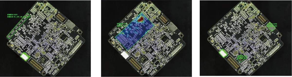
- For tiny parts, prioritize resolution and, if necessary, reduce the field of view and image by region
- For glossy surfaces, use a diffuser dome or polarization to control the reflection direction
- In tight spaces, consider miniature lenses or borescope-style imaging solutions
OK / NG Judgement
How results are judged and used
| Inspection Status | judgement | Interlocking Action |
|---|---|---|
| Assembly and appearance both pass | OK | release |
| Missing part or appearance defect present | NG | Isolate and Rework |
| Consecutive Defects | Alarm | Prompt upstream station check |
PLC and Automation Interlocking
How results connect to the production line
For lines with frequent changeovers, it is recommended that Recipe Switching Make it an action issued by the host system to reduce errors caused by manual selection.
For serial number verification, interlocking with MES is recommended so validation rules are not maintained on the equipment side.
Applicable equipment
Common configuration forms for this type of inspection
Related Solutions
View the corresponding solution by inspection task
Common Question
The Questions Most Often Asked in This Industry
Can parts this small really be detected?
Whether a part can be detected depends on how many pixels it occupies in the image. A 1 mm part can be imaged clearly with a suitable optical configuration; the key is to reduce the field of view or increase the resolution, and to ensure stable focus. It must be verified with the actual workpiece.
Changeovers are frequent — can the inspection solution keep up?
Make the inspection regions and acceptance criteria of each machine model a separate recipe, called up when the model is changed. A large number of recipes creates management issues, so it is recommended to also set up a recipe version management mechanism.
For visual inspection in this industry, what needs to be solved first?
The implementation constraints commonly seen in this industry center on: "parts are extremely small, placing high demands on resolution and focus"; "the assembly space is compact, making viewing angles hard to arrange"; "high-gloss surfaces (glass, mirror-finish metal) reflect strongly". These constraints affect both the imaging solution and the cycle-time design. Normally a sample trial is needed to validate before the configuration is finalized.
How does the inspection result interlock with the production line?
For production lines with frequent model changes, we recommend making recipe switching an action issued by the host system to reduce errors from manual selection. Serial number verification should interlock with MES to avoid maintaining verification rules on the equipment side.
What Equipment Configuration Does This Type of Inspection Generally Require?
Common forms include: "EEK-SV5205C industrial vision presence/absence inspection equipment", "high-resolution inspection station", "multi-view inspection cell". The specific machine model and quantity depend on the inspection area, the minimum defect size and the line cycle time, and must be confirmed according to the site conditions.
Which process steps in this industry benefit most from a visual inspection station?
The most common are: "screening for missing small screws and clips"; "connector and FPC mating confirmation"; "appearance anomaly identification". Which process steps to actually instrument depends on the cost of defects escaping downstream and the cost of rework — the later a defect is found, the higher the cost.
How do we judge whether our product is suitable for visual inspection?
Please provide assembly photos of the products to be inspected, the minimum part dimension and the changeover frequency, and our engineers will evaluate the required resolution and recipe management approach. Generally, as long as the criteria can be stated clearly, defects can image clearly and consistently, and the cycle time matches the field of view, the project is feasible.
What inspection accuracy can be achieved?
Accuracy is not a fixed value that holds regardless of conditions. To be added — the minimum detectable size depends on the combination of field of view and camera resolution, and is also affected by illumination, lens and algorithm; the configuration must be derived from your minimum defect size and validated by measurement.
Submit sample testing
Please provide assembly photos of the product to be inspected, the smallest part size and the changeover frequency, and our engineers will assess the required resolution and the recipe management approach.
Submitted successfully
We have received your sample testing request. A solution engineer will contact you within 1 business day via contact you.
Need to assess imaging conditions, defect criteria and cycle time item by item? Go to the Full Requirement Assessment →
Inspection Configuration Based on Your Industry's Products and Cycle Time
Send us photos of the workpiece, the inspection requirement (what to inspect, and the tolerance for escapes and false calls), and the line cycle time, and our solution engineers will recommend the inspection method, optical solution, and interlocking configuration for that industry.