Defense Composite Material AI Visual Inspection Equipment
Defense composite material AI visual inspection equipment: for composite materials such as carbon fiber, fiberglass, prepreg and honeycomb panels, it detects cracks, delamination, porosity, fiber misalignment, foreign matter and surface defects, outputs OK/NG, and supports process records and traceability.
Products Overview
Defects in composite materials are often internal, so the imaging method sets the limit of inspection
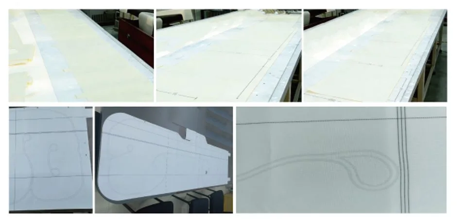
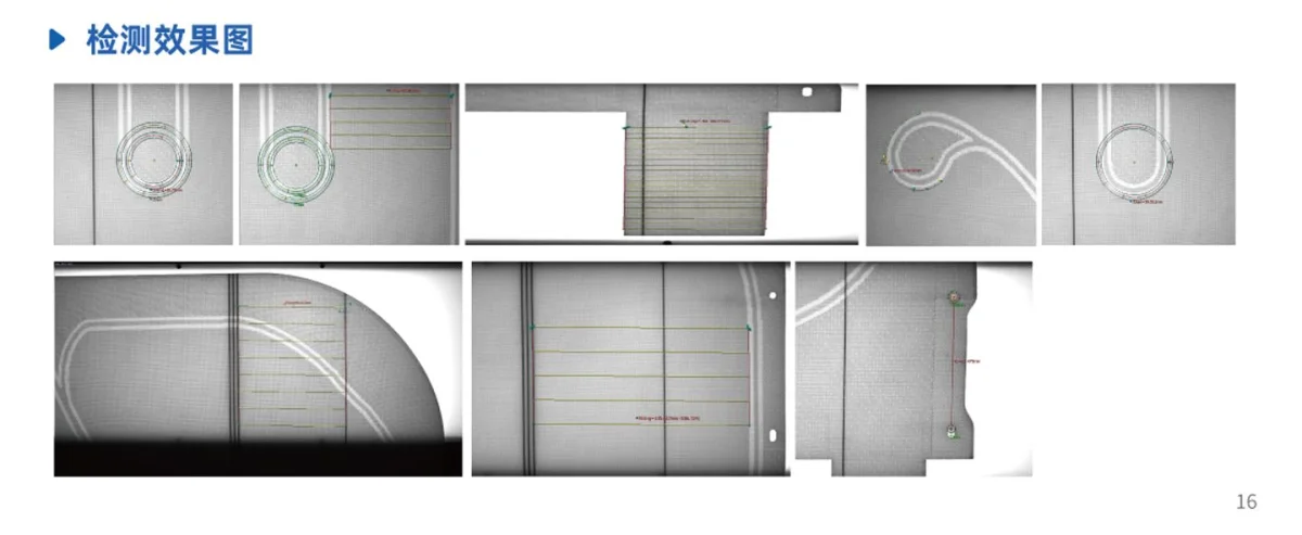
Defense composite material AI visual inspection equipment is used for appearance and surface defect inspection of composite materials such as carbon fiber, fiberglass, prepreg and honeycomb panels; it uses industrial cameras and application-specific lighting to identify cracks, delamination, porosity, fiber misalignment and foreign matter, outputs OK/NG and retains inspection images for traceability.
Composite material defects fall into two categories: surface defects and internal defects. Surface defects (scratches, foreign matter, fiber misalignment, resin starvation and resin-rich areas) can be inspected directly with industrial vision; internal defects (delamination, porosity, internal cracks) usually require ultrasonic, X-ray or infrared methods.
Therefore, the correct positioning of composite material visual inspection is: Handles fast full inspection of surface and near-surface defects, rather than claiming it can replace all non-destructive testing methods. Only when the boundary is stated clearly does the solution hold up.
At the surface inspection layer, the value of AI vision lies in handling "defects with irregular morphology" — crack paths are random, fiber misalignment takes many forms, and foreign matter comes in many varieties, all of which are hard to enumerate with fixed rules.
- Inspection boundary: surface and near-surface defects (internal defects require non-destructive testing)
- Typical defects: cracks, fiber misalignment, porosity, resin-starved and resin-rich areas, foreign matter, and scratches
- Materials: carbon fiber, fiberglass, prepreg, honeycomb panel, aramid
- Value: 100% inspection, consistent standards, traceable images
Core Functions
What the Equipment Can Do and How Far It Can Go
Full Surface Defect Inspection
Full-area inspection of composite material surfaces replaces manual visual checking.
Crack Recognition
Detecting cracks and micro-cracks with random orientations requires a sufficiently fine pixel scale.
Fiber direction deviation
Checks whether fiber orientation and ply direction deviate from the design requirements.
Porosity, Resin Starvation and Resin-Rich Areas
Judgement of visible surface pores and abnormal resin distribution.
Foreign Matter Inspection
Identifies mixed-in fibers, release film fragments and other foreign matter.
Image Trail
Inspection images and results are archived to support process traceability and batch management.
inspection Object
Unidirectional and Fabric Prepreg
Surface defect and foreign matter inspection of prepreg before layup
Laminated and Cured Parts
Surface defects, porosity and exposed fibers after curing
Honeycomb and Sandwich Structure
Panel surface defect and boundary area checks
Fibers and Fabrics
Fiber bundles, fabric appearance and weaving defects
inspection defect
| Defect Types | Inspection Feasibility | Description |
|---|---|---|
| Surface Crack | Detectable | Requires sufficient pixel resolution, direction is random |
| Fiber misalignment / direction deviation | Detectable | Depends on stable illumination and texture analysis |
| Porosity (Surface) | Detectable | Must be carefully distinguished from normal surface texture |
| Resin Starvation / Resin Rich | Detectable | Shows as local differences in gloss and texture |
| Foreign Matter / Inclusion | Detectable | Highly variable shapes, suitable for deep learning |
| Scratch / Indentation | Detectable | Low-angle illumination forms a clearer image |
| Internal Delamination | Not visually detectable | Requires ultrasonic, X-ray and other non-destructive testing methods |
| Internal Porosity | Not visually detectable | Requires ultrasonic, X-ray and other non-destructive testing methods |
Working Principles
- 01 Ply or product loading
- 02 Positioning and Flatness
- 03 Multi-angle illumination imaging
- 04 surface defect inspection
- 05 Fiber direction analysis
- 06 Foreign Matter Recognition
- 07 Result Composition OK / NG
- 08 Marking and Records
- 09 Data Archiving
Relationship Between Imaging and Judgement
The key prerequisite for visual inspection of composite materials is Clearly defining the inspection boundary. Industrial vision is good at surface and near-surface defects and can do nothing about internal defects. Only by stating this clearly can you avoid the argument at acceptance over "why the delamination was not detected".
Vision System
How Cameras, Lenses, Light Sources and Controllers Are Configured
industrial camera
Select area-scan or line-scan by field of view and minimum defect size; continuous web materials usually use line-scan cameras
- Area-scan camera: fixed-shot, single-piece and intermittent feed applications
- Line-scan camera: for continuous material travel, wide areas, and even-interval imaging
- Pixel equivalent is derived backwards from "minimum resolvable defect ÷ desired pixel count", rather than fixing the camera first
lens
Determines field of view, distortion, and depth of field; precision measurement requires telecentric lenses
- Standard industrial lens: low cost, suitable for appearance inspection
- Low-distortion lens: for large-format applications where the edges must also be judged
- Telecentric lens: suitable for hole diameter, contour and dimensional measurement
- Depth of field must match material waviness and fixture repeat positioning accuracy
Light Source and Illumination
Whether defects in flexible materials can be captured depends largely on the lighting
- Diffuse light: uniform illumination, suitable for color difference and stain applications
- Low-angle light: highlights scratches, indentations, wrinkles and other surface relief
- Backlight/transmitted light: highlights holes, damage and short shot
- Coaxial light / stripe light: suppresses reflection, suitable for coated or highly reflective surfaces
Controllers and Industrial PCs
The platform for running algorithms, outputting results and interlocking with the production line
- An industrial computer or vision controller runs the algorithms
- A light source controller handles brightness adjustment and strobe synchronization
- Interacts with the PLC to complete interlocking, alarming, and rejection
AI algorithm
Choose the Algorithm by Defect Form, Not by Complexity
Template Matching and Positioning
Locate first, then judge. Every defect judgment is built on a stable coordinate system.
- Shape matching / gray-scale matching: good stability, suitable for fixed stations
- Align first, then split the regions, to avoid false calls caused by position drift
Blob and Morphological Analysis
Suited to defects such as stains, holes and foreign matter that show a clear grayscale/color difference from the background
- Threshold segmentation → connected component statistics → judgement by area / aspect ratio / circularity
- High requirements on illumination stability; the light source must work with the fixture
Edge and Contour Measurement
Suitable for dimension, contour, hole position and spacing judgements
- Sub-pixel edge extraction to obtain a contour point set
- Fit lines/circles/arcs and calculate length, diameter, angle and position tolerance
Deep Learning (Classification / Detection / Segmentation)
Suited to defects such as scratches, wrinkles and skipped stitches, whose shapes vary and are hard to describe with rules
- When defect forms are irregular, it is difficult for rule-based algorithms to enumerate them all
- Requires OK / NG sample training; sample quantity and coverage determine the upper limit
- Enables pixel-level segmentation and outputs defect length, width, area and position
Automatic Alarm and rejection
How inspection results act on the production line
Inspection results are not only shown on a screen. Workpieces judged NG need to be Mark the position and interlock rejection or sorting, and archives the image and judgement result for that part for later traceability and re-judgement.
The alarm method is set according to site practice: audible and visual alarm, on-screen pop-up, PLC set bit, or all three at once. Critical defects and general defects can use different handling strategies — the former stops the machine and alarms, the latter is only marked.
- 01 image acquisition
- 02 Positioning and region segmentation
- 03 Defect Judgement
- 04 Combine results into a single OK / NG per piece
- 05 Result sent to PLC
- 06 NG Rejection / Sorting
- 07 Image and data archiving
data traceability
Records, Queries and Quality Closed Loop
Per-Piece Records
The judgment result, defect type, defect position and timestamp of every part are written to the database
- Supports retrieval by time, batch and defect type
- NG image retention for re-judgement
Batch and Recipe
Different products use different recipes, called up at changeover to reduce manual parameter tuning
- Recipes store the inspection region, thresholds and algorithm parameters
Production Line Data Integration
Exchange inspection data with the MES / host system
- Output pass rate, defect distribution and other statistics
- The interface method depends on the site system
equipment configuration
Optional Configuration Items and Selection Logic
| Configuration Item | Description |
|---|---|
| Applicable Materials | Carbon fiber / fiberglass / aramid / prepreg / honeycomb panel / composite panel |
| Inspection Scope | Surface and near-surface defects (internal defects require non-destructive testing) |
| Inspection Method | Industrial camera + reflection-suppressing illumination + AI algorithm |
| Inspection Speed | To be added |
| inspection accuracy | To be added |
| communication method | I/O · TCP · RS485 · Modbus · S7 · Profinet |
| Enclosure and Power Supply | To Be Confirmed on Site |
Application Industry
Which Industry This Equipment Is Usually Installed In
Applicable Materials
Detectable Material Types
Common Question
Can Delamination in Carbon Fiber Be Detected by Visual Inspection?
Can fiber orientation deviation be measured?
Are prepreg and cured products inspected the same way?
Does the Gloss of a Composite Material Surface Affect Imaging?
Can the Equipment Connect to an Automated Fiber Placement/Tape Laying Line?
What Information Do You Need to Provide?
Submit sample testing
Composite material defect types are diverse; we recommend providing physical samples with typical defects so that imaging feasibility validation can be done first, before discussing inspection items and acceptance criteria.
Submitted successfully
We have received your sample testing request. A solution engineer will contact you within 1 business day via contact you.
Need to assess imaging conditions, defect criteria and cycle time item by item? Go to the Full Requirement Assessment →
Send Us Your Workpiece and We Will Show You the Measured Results
Equipment configuration varies with the inspection object, field of view and cycle time. Provide OK and NG samples and we will run actual imaging and judgement tests and recommend the corresponding model and configuration.