FPC Stiffener Inspection
FPC stiffener inspection: for the short shot, bonding offset, dimensions, burrs and foreign matter of PI, FR4 and steel stiffeners, with imaging of the flexible board stiffener area + template matching and AI judgement outputting OK/NG.
Application Overview
FPC Stiffener Bonding Offset and Missing Material Inspection
Inspects short shot, bonding offset, dimensions, burrs, and foreign matter on FPC stiffeners (PI / FR4 / steel sheet); imaging is done on the stiffener area of the flexible board, with AI judging defects and measuring alignment.
FPC stiffeners locally reinforce flexible circuit boards; lamination offset, short shot and dimensional deviation lead to soldering or assembly defects. The stiffener area sits on a flexible substrate, so imaging must cover both flatness and alignment.
This station covers the appearance and dimensions of the FPC stiffener area, focusing on short shot, bonding offset, contour dimensions, burrs and foreign matter; comparison is made against the stiffener pattern template.
Inspection takes place after lamination, imaging one piece at a time; reinforcement materials (PI/FR4/steel sheet) differ in reflectivity, so illumination is adjusted by material and alignment uses template matching.
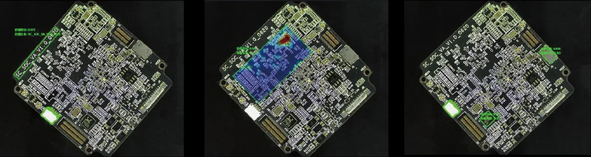

inspection Targets
What This Station Actually Has to Judge
| inspection item | Description |
|---|---|
| short shot | Reinforcement short shot, incomplete cutouts |
| Lamination Offset | Stiffener position offset |
| out-of-tolerance dimension | Stiffener length/width out of tolerance |
| Burr / Flash | Cutting Burr |
| foreign matter | Adhered Particles |
| stain | Oil Stains, Discoloration |
| Exposed Copper / Damage | Substrate Damage |
Why Inspect
Problems with manual visual inspection at this step
Bonding offset and short shot of FPC stiffeners most affect assembly; the stiffener area sits on a flexible substrate, so alignment accuracy is critical and template matching is needed to judge position.
Steel sheet reinforcement is highly reflective, and poor illumination can make reflections look like defects; different materials need lighting tuned separately.
- Lamination offset and short shots affect assembly
- Alignment accuracy in the stiffener area is critical
- Steel sheet glare causes false calls
- Different materials require separate illumination tuning
How Inspect
Stations and Inspection Chain
- 01 Load and fix the FPC
- 02 Tune lighting and imaging by material
- 03 Template matching for the stiffener area
- 04 Short shot judgement
- 05 Lamination offset measurement
- 06 Telecentric Dimension Measurement
- 07 Burr and foreign matter segmentation
- 08 OK/NG output
- 09 Image and data archiving
How to Inspect
The FPC stiffener area is imaged with an area-scan camera; the stiffener pattern is used for template matching and positioning, steel plates use coaxial/stripe light to suppress reflection, and dimensions are measured with a telecentric lens — template matching + dimensional imaging.
inspection defect
| Defect Types | Typical Manifestations | Inspection Focus Points |
|---|---|---|
| short shot | Missing Stiffener | Template Comparison |
| Lamination Offset | Position Offset | template matching |
| out-of-tolerance dimension | Length/Width Out of Tolerance | Telecentric Measurement |
| burr | Cutting Flash | Low-Angle Light |
| foreign matter | Particles | Segmentation |
| stain | Oil Stains, Discoloration | Diffused Light |
| Substrate Damage | Exposed Copper Scratch | Segmentation |
Applicable equipment
Application Industry
Common Question
What Are the Key Points in FPC Stiffener Inspection?
Can it replace manual labor?
What Inspection Accuracy Can Be Achieved?
How Do You Image Reflective Steel Stiffeners?
How Is Bonding Offset Judged?
Are results traceable?
Do I Need to Re-Tune When the Stiffener Pattern Changes?
Submit sample testing
Typical OK/NG FPC reinforcement samples can be sent for measurement: the lighting and template matching scheme is determined by the reinforcement material.
Submitted successfully
We have received your sample testing request. A solution engineer will contact you within 1 business day via contact you.
Need to assess imaging conditions, defect criteria and cycle time item by item? Go to the Full Requirement Assessment →
Can This Application Be Done? Sending a Sample for Testing Is the Most Direct Answer
Incoming material, part orientation and cycle time vary widely from factory to factory. Send us real samples and we will run imaging and judgement validation against your production line conditions, then give you a configuration proposal you can actually implement.