Aerospace Materials AI Visual Inspection Equipment
Aerospace materials AI visual inspection equipment: for aerospace composite materials, prepreg, honeycomb panels and aircraft interior parts, it detects surface cracks, fiber misalignment, porosity, foreign matter and ply defects, outputs OK/NG and retains inspection images for traceability.
Products Overview
Surface quality during the prepreg lay-up stage directly affects the quality of subsequent curing
The aerospace materials AI visual inspection equipment is used for surface defect inspection of aerospace composite materials, prepreg and honeycomb panels. Using industrial cameras and dedicated lighting it identifies cracks, fiber misalignment, porosity, foreign matter and layup anomalies, outputs OK/NG and retains full-area images for quality traceability.
The quality control chain for aerospace composites is long: incoming material inspection, lay-up, curing, machining, assembly and non-destructive testing. The stages where visual inspection can fit in are mainly Surface quality control at the incoming material and lay-up stages, as well as surface inspection after forming.
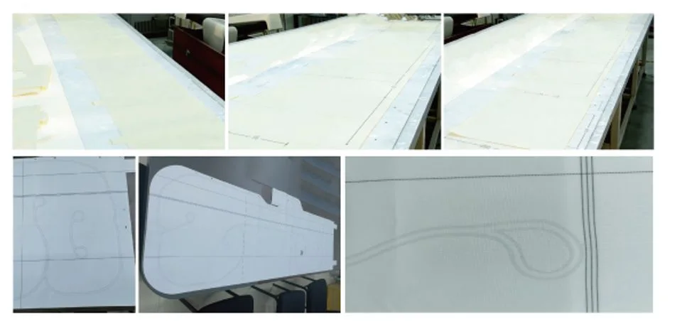
Prepreg layup is a particularly critical step. If foreign matter is trapped, the fiber direction deviates, wrinkles appear or the overlap is incorrect during layup, it is very hard to correct after curing and the whole part often has to be scrapped. Adding a visual inspection step at the layup stage can significantly reduce later losses.
In aerospace, inspection requirements go beyond accuracy and include Traceable: the inspection images and results for every part and every layer must be retained and must correspond to the process records. This is also a part that must be considered in solution design.
- Entry points: incoming material inspection / ply layup check / post-forming surface check
- Typical defects: foreign matter, fiber misalignment, wrinkles, improper overlap, and surface cracks
- Inspection boundary: surface and near-surface; internal defects require non-destructive testing
- Additional requirement: images and results traceable
Core Functions
What the Equipment Can Do and How Far It Can Go
Ply Foreign Matter Inspection
During the lay-up process, check for mixed-in release film fragments, fibers and particulate foreign matter.
Fiber Direction Inspection
Texture direction analysis determines whether the lay-up direction deviates from the process requirement.
Wrinkle and Overlap Inspection
Identifies wrinkles, poor overlaps and local build-up in prepreg.
Surface Crack Inspection
Surface crack and scratch inspection on formed parts requires sufficient pixel equivalent.
Full-Area Image Retention
Inspection images are retained for each part and can be traced back against process records.
Coordination with Layup Equipment
Can be interlocked with automated fiber placement / tape laying equipment for inline inspection.
inspection Object
Prepreg and Ply Layup
Surface quality and foreign matter checks at the lay-up stage
Molded Structural Parts
Surface cracks, porosity and exposed fibers after curing
Honeycomb and Sandwich Structures
Panel surface and boundary area check
Interior Trim and Seat Parts
Surface quality of aircraft interior and seat components
inspection defect
| Defect Types | Inspection Feasibility | Description |
|---|---|---|
| Foreign Matter / Inclusion | Detectable | The most critical type at the lay-up stage |
| Fiber direction deviation | Detectable | Depends on a clear fiber texture |
| Wrinkle / poor overlap | Detectable | Distinct surface morphology |
| Surface Crack | Detectable | Requires sufficient pixel equivalent |
| Porosity (Surface) | Detectable | Must be distinguished from normal texture |
| Scratch / Indentation | Detectable | Low-angle illumination forms a clearer image |
| Internal Delamination | Not visually detectable | Ultrasound / X-ray methods required |
Working Principles
- 01 Incoming material or ply loading
- 02 Positioning and Flatness
- 03 Zoned Imaging
- 04 Foreign Matter Recognition
- 05 Fiber direction analysis
- 06 Wrinkle and overlap judgement
- 07 Surface defect judgement
- 08 Result Composition OK / NG
- 09 Image and result archiving
Relationship Between Imaging and Judgement
Visual inspection of aerospace composites has two hard prerequisites: first, The imaging area must provide complete coverage, with no blind spots; second, Images must correspond to the workpiece and layer number, otherwise the traceability chain breaks. These two points are often harder to achieve than the algorithm itself.
Vision System
How Cameras, Lenses, Light Sources and Controllers Are Configured
industrial camera
Select area-scan or line-scan by field of view and minimum defect size; continuous web materials usually use line-scan cameras
- Area-scan camera: fixed-shot, single-piece and intermittent feed applications
- Line-scan camera: for continuous material travel, wide areas, and even-interval imaging
- Pixel equivalent is derived backwards from "minimum resolvable defect ÷ desired pixel count", rather than fixing the camera first
lens
Determines field of view, distortion, and depth of field; precision measurement requires telecentric lenses
- Standard industrial lens: low cost, suitable for appearance inspection
- Low-distortion lens: for large-format applications where the edges must also be judged
- Telecentric lens: suitable for hole diameter, contour and dimensional measurement
- Depth of field must match material waviness and fixture repeat positioning accuracy
Light Source and Illumination
Whether defects in flexible materials can be captured depends largely on the lighting
- Diffuse light: uniform illumination, suitable for color difference and stain applications
- Low-angle light: highlights scratches, indentations, wrinkles and other surface relief
- Backlight/transmitted light: highlights holes, damage and short shot
- Coaxial light / stripe light: suppresses reflection, suitable for coated or highly reflective surfaces
Controllers and Industrial PCs
The platform for running algorithms, outputting results and interlocking with the production line
- An industrial computer or vision controller runs the algorithms
- A light source controller handles brightness adjustment and strobe synchronization
- Interacts with the PLC to complete interlocking, alarming, and rejection
AI algorithm
Choose the Algorithm by Defect Form, Not by Complexity
Template Matching and Positioning
Locate first, then judge. Every defect judgment is built on a stable coordinate system.
- Shape matching / gray-scale matching: good stability, suitable for fixed stations
- Align first, then split the regions, to avoid false calls caused by position drift
Blob and Morphological Analysis
Suited to defects such as stains, holes and foreign matter that show a clear grayscale/color difference from the background
- Threshold segmentation → connected component statistics → judgement by area / aspect ratio / circularity
- High requirements on illumination stability; the light source must work with the fixture
Edge and Contour Measurement
Suitable for dimension, contour, hole position and spacing judgements
- Sub-pixel edge extraction to obtain a contour point set
- Fit lines/circles/arcs and calculate length, diameter, angle and position tolerance
Deep Learning (Classification / Detection / Segmentation)
Suited to defects such as scratches, wrinkles and skipped stitches, whose shapes vary and are hard to describe with rules
- When defect forms are irregular, it is difficult for rule-based algorithms to enumerate them all
- Requires OK / NG sample training; sample quantity and coverage determine the upper limit
- Enables pixel-level segmentation and outputs defect length, width, area and position
Automatic Alarm and rejection
How inspection results act on the production line
Inspection results are not only shown on a screen. Workpieces judged NG need to be Mark the position and interlock rejection or sorting, and archives the image and judgement result for that part for later traceability and re-judgement.
The alarm method is set according to site practice: audible and visual alarm, on-screen pop-up, PLC set bit, or all three at once. Critical defects and general defects can use different handling strategies — the former stops the machine and alarms, the latter is only marked.
- 01 image acquisition
- 02 Positioning and region segmentation
- 03 Defect Judgement
- 04 Combine results into a single OK / NG per piece
- 05 Result sent to PLC
- 06 NG Rejection / Sorting
- 07 Image and data archiving
data traceability
Records, Queries and Quality Closed Loop
Per-Piece Records
The judgment result, defect type, defect position and timestamp of every part are written to the database
- Supports retrieval by time, batch and defect type
- NG image retention for re-judgement
Batch and Recipe
Different products use different recipes, called up at changeover to reduce manual parameter tuning
- Recipes store the inspection region, thresholds and algorithm parameters
Production Line Data Integration
Exchange inspection data with the MES / host system
- Output pass rate, defect distribution and other statistics
- The interface method depends on the site system
equipment configuration
Optional Configuration Items and Selection Logic
| Configuration Item | Description |
|---|---|
| Applicable Materials | Carbon fiber prepreg / aerospace composite materials / honeycomb panels / interior parts |
| Inspection Step | Incoming inspection / ply lay-up check / post-molding surface check |
| Inspection Method | Industrial camera + reflection-suppressing illumination + AI algorithm |
| Recording Method | Archived by batch / workpiece number (customized on request) |
| Inspection Speed | To be added |
| inspection accuracy | To be added |
| communication method | I/O · TCP · RS485 · Modbus · S7 · Profinet |
| Enclosure and Protection | Confirm according to site conditions |
Application Industry
Which Industry This Equipment Is Usually Installed In
Applicable Materials
Detectable Material Types
Common Question
Are Inspection Standards for Aerospace Composites the Same as for Commercial Products?
Can inspection be done in real time during the lay-up process?
Is wrinkle detection on prepreg difficult?
How long do inspection images need to be stored?
Does the equipment have installation environment requirements?
What Information Do You Need to Provide?
Submit sample testing
The inspection boundary for aerospace composite materials needs to be defined clearly first. We recommend providing typical samples and acceptance criteria; we will run a feasibility validation first and then discuss the scope of the solution.
Submitted successfully
We have received your sample testing request. A solution engineer will contact you within 1 business day via contact you.
Need to assess imaging conditions, defect criteria and cycle time item by item? Go to the Full Requirement Assessment →
Send Us Your Workpiece and We Will Show You the Measured Results
Equipment configuration varies with the inspection object, field of view and cycle time. Provide OK and NG samples and we will run actual imaging and judgement tests and recommend the corresponding model and configuration.