Assembly Confirmation: Verifying Assembly State Before Release
Confirms that every required component is present and correctly seated before the product leaves the station, signalling OK/NG to the line.
Solution Overview
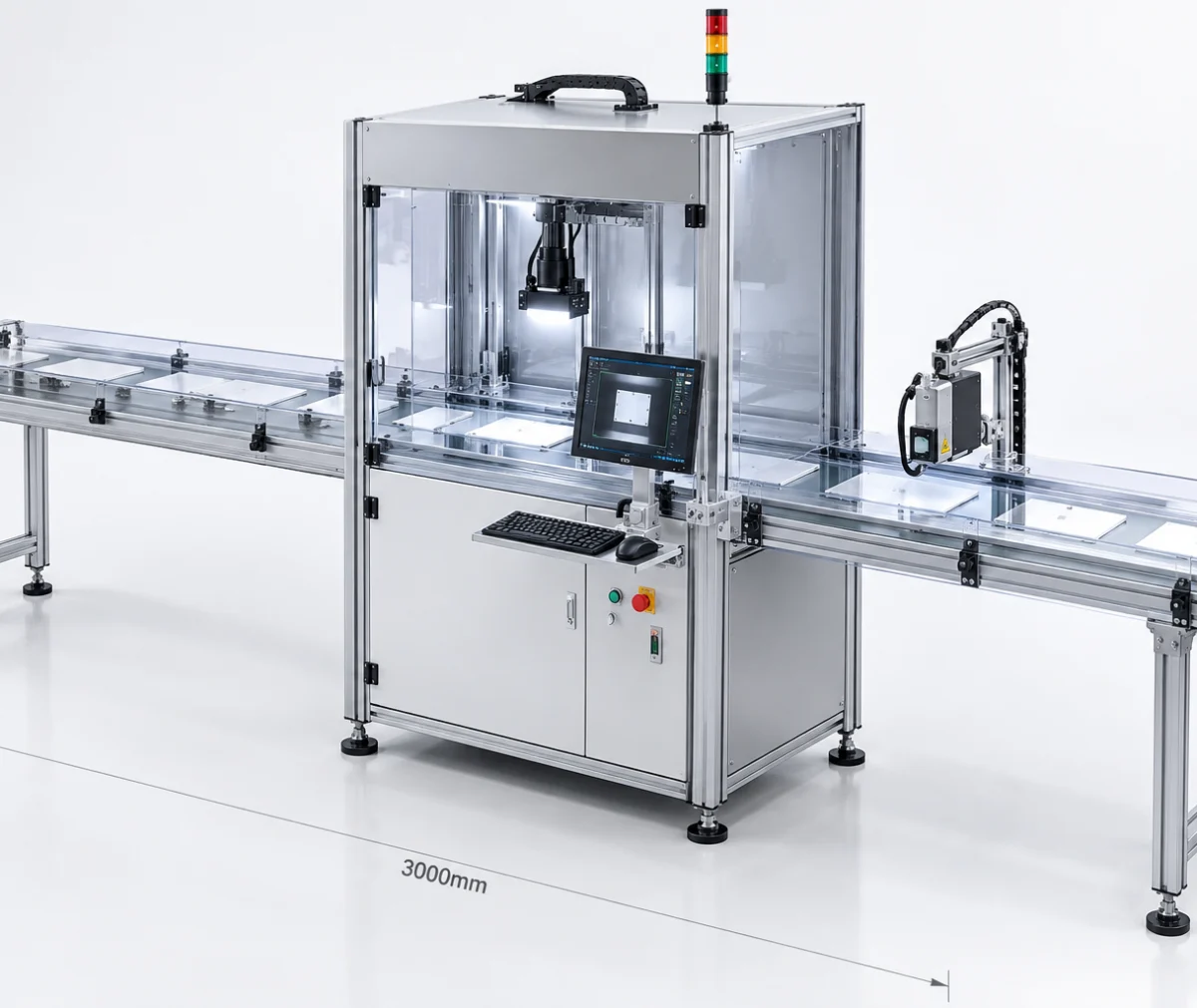
Assembly state visual confirmation: determines whether assembly actions are truly in place — whether press-fitting is pressed home, whether fastening is tightened, whether connectors are inserted fully — distinguishing "assembled" from "assembled correctly". The solution consists of three parts: imaging, algorithm, and interlocking; the judgement threshold must be biased according to the asymmetric cost of escapes and false rejections, and is subject to the results of a measured sample trial.
"Installed" and "installed correctly" are two different things. A press fit that is a few hundredths of a millimeter off, a connector that is one detent short, a clip that is not pushed fully home — all of these may look fine on the outside, but in later use they show up as poor contact, noise, seal failure or premature failure.
The task of assembly confirmation is to take this kind of "Slightly off" states are picked out. Common acceptance criteria include: overall height or flushness after assembly, step / gap features at joints, the relative position of seating marks (scribed lines, color marks), and the fit condition between mating parts.
inspection Content
Items to verify on site for "assembly state visual confirmation", listed by common case
Press-Fit Seating Confirmation
- Bearing Press-Fit Depth
- Bushing Fully Press-Fitted
- Dowel Pin Press-In Depth
- Seal Pressed Fully In Place
Screw-Fastening Seating Confirmation
- Screw Tightened in Place
- Thread engagement
- Clamp Tightened
- Rivet Fully Seated
Insertion Seating Confirmation
- Connector Fully Inserted
- Terminal Fully Crimped
- Pipe Fitting Fully Tightened
- Flat Cable Fully Inserted
Snap-Fit Seating Confirmation
- Clip Engaged
- Housing Closed
- Cover Plate Fully Pressed
- Latch Closed
Attachment Seating Confirmation
- Label Applied Flat
- Foam Attached
- Tape application
- Insulation Sheet Fully Attached
Position Seating Confirmation
- Part at the datum position
- Uniform gap
- Consistent flushness
- Visual abnormality in coaxiality
inspection Method
From trigger and acquisition to result output, how the judgement is produced
- 01 Workpiece-in-Place Trigger
- 02 image acquisition
- 03 Datum positioning
- 04 Seating Feature Extraction
- 05 Compare with the standard state
- 06 Judge Whether Fully Seated
- 07 Output OK / NG
- 08 PLC interlocking
- 09 Release / interception
The most common technical approach for seating judgement is Measurement-based judgement: measure a quantity in the image that reflects the assembly depth (such as the length of shaft exposed after press-fitting, the gap width after snapping together, or the distance from the in-place mark to the datum), then compare this quantity with the acceptable range.
Compared with whole-image comparison that asks "does it look the same", the advantage of measurement-based judgment is Acceptance criteria can be quantified, given tolerances and traced. The prerequisite is that this physical quantity can be measured reliably in the image — which brings us back to optics and mounting angle.
judgement and Interlocking
How results are judged and passed to the production line
| Seating Acceptance Criteria | Acceptable Range Example | judgement |
|---|---|---|
| Alignment marks coincide when fully seated | Mark alignment within the tolerance band | OK |
| Mark does not reach the seated line | Deviation beyond tolerance on the non-accepting side | NG |
| Mark passes the seating line (over-pressed) | Deviation beyond tolerance on the non-accepting side | NG |
Note that the range is two-sided: Improper seating is a defect, and over-pressing is equally a problem. Acceptance criteria should set both an upper and a lower limit, rather than only a "not less than".
The dimensional ranges in the table above are only examples of the form of acceptance criteria; the actual tolerances must come from the product drawing or process documentation and must not be assumed from experience.
Related Inspection Objects
View more specific object characteristics, acceptance criteria and optical notes by object
Applicable Industry
Scenarios in These Industries That Already Have Corresponding Inspection Needs
Common Question
Questions most often asked during selection and implementation
How Much Accuracy Does Assembly Seating Inspection Require?
Accuracy requirements should be derived backwards from the product tolerance, rather than starting from a "the more accurate the better" target. If the positioning tolerance on the drawing is ±0.5 mm, it is enough for the measurement repeatability of the inspection system to be clearly better than that order of magnitude; pushing accuracy higher than necessary brings unnecessary cost.
Can vision measure press-fit depth?
Yes for many structures, provided that a feature reflecting depth can be imaged (such as the exposed length of a shaft or the position of a press-fit shoulder). If that feature is occluded or not visible, consider changing the tooling, adding a side camera or switching to another sensing method (such as a displacement sensor) rather than forcing vision to do the job.
What are the advantages compared with manual confirmation?
The quality of manual confirmation fluctuates with fatigue and cycle time, whereas visual confirmation applies the same set of acceptance criteria every time. In addition, the results of visual confirmation can be retained as image evidence for later traceability and process improvement, which manual confirmation can hardly achieve.
How are the acceptance criteria for this solution defined?
Note that the range is two-sided: an incomplete assembly is a defect, and over-pressing is equally a problem. The acceptance criteria should set both an upper and a lower limit, rather than only a "not less than". The dimension ranges in the table above are only examples of the form of the criteria; the specific tolerances must come from the product drawing or process documents and cannot be assumed from experience.
What is the inspection method?
The most common technical route for seating judgement is measurement-based judgement: use the image to measure a quantity that reflects assembly depth (such as the length of shaft exposed after press-fitting, the gap width after snapping together, or the distance from the seating mark to the datum), then compare this quantity with the acceptable range. Compared with whole-image comparison that asks "does it look alike", the advantage of measurement-based judgement is that the criteria can be quantified, tolerances can be set and results can be traced. The prerequisite is that this physical quantity can be measured consistently in the image — which brings us back to the questions of optics and mounting angle.
Which Inspection Objects Is This Solution Applicable To?
View the object characteristics, acceptance criteria and optical considerations for each object; it covers 8 common object types including gasket presence/absence inspection, spring presence/absence inspection, seal ring presence/absence inspection and dowel pin presence/absence inspection.
Can this solution replace manual labor?
What visual inspection replaces is repetitive visual judgement, not manual labor for everything. The typical division of labor is: vision performs part-by-part full inspection and judgement, while people handle re-judgement of borderline samples, changeovers and exceptions, and maintenance of the optics and tooling. How many people are actually involved depends on the degree of automation and the re-judgement strategy.
How do you verify that this solution is feasible?
Please provide photos of the assembled in-place state (including conforming parts and the common not-fully-seated parts), together with the in-place tolerance requirement from the drawing; an engineer will judge whether that acceptance criterion can be measured stably in the image.
Submit sample testing
Please provide photos of the assembled in-place state (including conforming parts and the common not-fully-seated parts), together with the in-place tolerance requirement from the drawing; an engineer will judge whether that acceptance criterion can be measured stably in the image.
Submitted successfully
We have received your sample testing request. A solution engineer will contact you within 1 business day via contact you.
Need to assess imaging conditions, defect criteria and cycle time item by item? Go to the Full Requirement Assessment →
Submit Samples to Get a Visual Inspection Solution
Tell us the workpiece, inspection requirements, production line cycle time and your existing PLC / communication method, and our solution engineers will recommend the inspection method, optical configuration and interlocking solution.