Vision-Based Part Counting
Counts parts in a tray, bag or bundle and verifies the number against the order, without contact and without manual recount.
Solution Overview
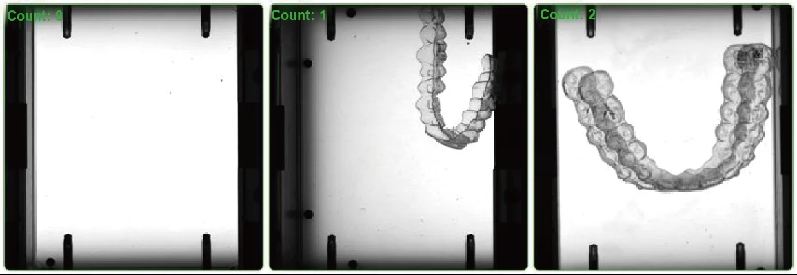
Industrial vision count inspection: automatically counts and verifies the number of parts on a product or inside packaging, suitable for scenarios such as screw count, attachment count, the number of parts in a multi-cavity workpiece, and the number of items in a package. The solution consists of three parts: imaging, algorithm, and interlocking; the judgement threshold must be biased according to the asymmetric cost of escapes and false rejections, and is subject to the results of a measured sample trial.
The difference between count inspection and presence/absence inspection is that The acceptance criteria are a number, not a state. It answers how many there are, and then compares that with the expected count.
This brings two additional requirements: first, the target must be able to Separated one by one (they must not merge into a clump), and second, the counting rule must be explicit (whether overlapping items count as one or two, and whether occluded items count). These two points determine whether count inspection is feasible and what tooling and illumination it needs.
inspection Content
Items to verify on site for "industrial vision count inspection", listed by common case
Fastener counting
- Screw count
- Nut count
- Gasket count
- Spring washer count
Attachment Counting
- Accessory pack piece count
- Instruction manual page count
- Tool count
- Gift item count
Multi-pocket counting
- Whether fixture pockets are fully loaded
- Tray Station Counting
- Material Box Slot Counting
- Multi-Cavity Product Counting
Counting inside the package
- Bagged item count
- Boxed item count
- Blister tray piece count
- Full-Carton Count Verification
Electronic part counting
- Terminal block pole count
- Pin header position count
- Connector position count
- PCB component count
Continuous Material Strip Counting
- Missing position in carrier tape
- Empty position in tape
- Missing chain link
- Break point between connected parts
inspection Method
From trigger and acquisition to result output, how the judgement is produced
- 01 Workpiece / Packaging in Place
- 02 image acquisition
- 03 Target segmentation or region partitioning
- 04 Target-by-target recognition
- 05 Deduplication and merging rules
- 06 Count the Measured Quantity
- 07 Compare with the expected count
- 08 Output OK / NG
- 09 PLC interlocking
The difficulty in count inspection is usually not the algorithm but Separability of the target. Parts tightly packed in the same field of view, parts overlapping each other and parts merged into one blob by reflection all make the counting rule ambiguous.
The engineering approach is usually "solve imaging first, then solve the algorithm": use illumination (backlight, low angle, dark field) to create a distinguishable boundary between targets, or use tooling to keep a fixed spacing between parts. Once the targets are separated, counting becomes a straightforward process.
judgement and Interlocking
How results are judged and passed to the production line
| Measured Count | judgement | Interlocking Action |
|---|---|---|
| Equal to the Required Count | OK | release |
| Less Than the Required Count | NG | Treated as a missing part; part added or quarantined |
| More Than the Required Count | NG | Handled as extra parts and equally rejected |
Extra parts must be stopped as well: a surplus part can cause interference, short circuits or assembly difficulties in later process steps, and must not be passed just because "at least nothing is missing".
If the site only needs to know "is it enough" rather than an exact count, the acceptance criteria can be simplified to "no fewer than N", which lowers the demands on target segmentation and makes the implementation cost more controllable.
Related Inspection Objects
View more specific object characteristics, acceptance criteria and optical notes by object
Applicable Industry
Scenarios in These Industries That Already Have Corresponding Inspection Needs
Common Question
Questions most often asked during selection and implementation
Can overlapping parts be counted accurately?
Overlap significantly increases the difficulty of counting. There are two workable paths: first, improve the tooling or the way parts are tipped out so that parts overlap as little as possible; second, accept that "overlapping areas cannot be judged" and convert them into an alarm or manual review. We do not recommend promising exact counts directly in scenarios with severe overlap.
Can parts be counted on a fast-moving production line?
It depends on the relationship between the motion speed and the required exposure time. The higher the speed, the shorter the available exposure time and the higher the demands on illumination brightness and stability. The real usable speed limit must be measured on site, not extrapolated from a specification sheet.
How are transparent or reflective parts counted?
Transparent parts usually need special illumination (such as backlight + polarization, or dark field) to make the edges visible; reflective parts use angle, polarization, or diffuse lighting to reduce specular reflection. The feasibility for such parts must be validated with actual imaging tests and cannot be judged from experience alone.
How are the acceptance criteria for this solution defined?
An extra part must also be stopped — a surplus part can cause interference, short circuits, or assembly difficulties in subsequent process steps, and must not be let through just because "at least nothing is missing". If the site only needs to know whether there are "enough" rather than an exact count, the acceptance criteria can be simplified to "no fewer than N", which lowers the demand on target segmentation and makes the implementation cost more controllable.
What is the inspection method?
The difficulty in count inspection is usually not the algorithm but the separability of the targets. Parts packed tightly in the same field of view, parts overlapping each other, and parts joined into one blob by reflections all make the counting rule ambiguous. The engineering solution is usually "solve imaging first, then the algorithm": use illumination (backlight, low angle, dark field) to create a distinguishable boundary between targets, or use tooling to keep a fixed spacing between parts. Once the targets are separated, counting is a straightforward process.
Which Inspection Objects Is This Solution Applicable To?
View the more specific object characteristics, acceptance criteria and optical considerations by object; covers 8 common object types including screw presence/absence inspection, nut presence/absence inspection, gasket presence/absence inspection and PCB component presence/absence inspection.
Can this solution replace manual labor?
What visual inspection replaces is repetitive visual judgement, not manual labor for everything. The typical division of labor is: vision performs part-by-part full inspection and judgement, while people handle re-judgement of borderline samples, changeovers and exceptions, and maintenance of the optics and tooling. How many people are actually involved depends on the degree of automation and the re-judgement strategy.
How do you verify that this solution is feasible?
Please provide the parts to be counted and the packaging / tooling format, and explain the counting rules (for example how overlaps are handled); the engineer will assess target separability and give imaging recommendations.
Submit sample testing
Please provide the parts to be counted and the packaging / tooling format, and explain the counting rules (for example how overlaps are handled); the engineer will assess target separability and give imaging recommendations.
Submitted successfully
We have received your sample testing request. A solution engineer will contact you within 1 business day via contact you.
Need to assess imaging conditions, defect criteria and cycle time item by item? Go to the Full Requirement Assessment →
Submit Samples to Get a Visual Inspection Solution
Tell us the workpiece, inspection requirements, production line cycle time and your existing PLC / communication method, and our solution engineers will recommend the inspection method, optical configuration and interlocking solution.