Detecting the Wrong Part or Wrong Orientation
Detects the wrong part or the wrong orientation by the feature that actually distinguishes the models - colour, marking, geometry or direction.
Solution Overview
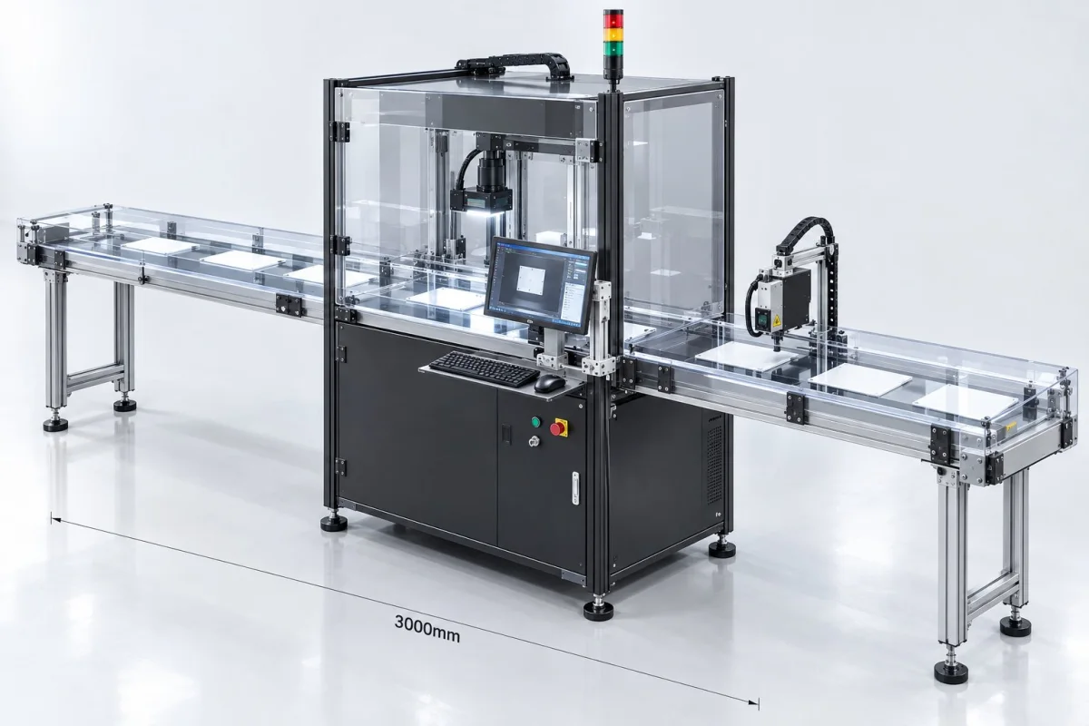
Visual inspection for wrong assembly: at the assembly process step, it judges whether a part is of the wrong model, installed in reverse or in the wrong position; it applies to assembly scenarios with multiple models on a mixed line and easily confused similar parts, and outputs OK/NG to interlock with the production line for poka-yoke. The solution consists of three parts, imaging, algorithm and interlocking, and the judgement threshold must be biased according to the asymmetric costs of escapes and false rejections, and is subject to the results of a measured sample trial.
A wrong part is a harder problem to prevent than a missing part: The part is installed, but it is the wrong part — wrong model, reversed orientation, part in the wrong position. Manual visual inspection is the most likely to let these through, because visually "something is there" and it is easily treated as conforming.
The acceptance criteria for wrong-part inspection must be based on Distinguishable difference features and: differences in outer shape, color, characters, orientation features (notches, chamfers, marking points), or the relative positional relationship between adjacent parts. If no stable distinguishing feature can be found, there is no basis for visual mistake-proofing.
inspection Content
Items to verify on site for "assembly wrong part visual inspection", listed by common case
Wrong Model Installed
- Mixed Similar Specifications
- Mixed models on one line
- Mixing old and new material
- Wrong Batch Material
Reversed Orientation
- Reversed Front/Back
- Reversed Inside/Outside
- Upside Down
- Front/Back Reversed
Wrong Position
- Wrong Part Installed at Left/Right Station
- Hole Position Deviation
- Assembly positions mixed up
- Installed in the adjacent position
Wrong color / material
- Mixed color parts
- Different Material
- Coating Difference
- Genuine parts mixed with substitutes
Character Mismatch
- Incorrect Model Printing
- Batch code mismatch
- Wrong orientation marking
- Label Content Mismatch
Mismatched Pairing
- Left and right fittings do not match
- Reversed Harness Connection
- Pipe fitting specification mismatch
- Mixed-Batch Assembly
inspection Method
From trigger and acquisition to result output, how the judgement is produced
- 01 Workpiece-in-Place Trigger
- 02 Read Model / Recipe
- 03 image acquisition
- 04 Target positioning and alignment
- 05 Difference Feature Extraction
- 06 Compare with the standard features
- 07 Output OK / NG
- 08 PLC interlocking
- 09 Quarantine / Release
The technical core of wrong part inspection is Choosing the Right Difference Features. For the same part, if two models differ by only 0.2 mm in outer diameter, distinguishing them by external dimensions is very demanding; but if the two models have different colors, or are the same part fitted in a different assembly orientation, color or orientation features are far more reliable.
In engineering, the order is: first list all the models / states that need to be distinguished, then find the differences between them The most obvious visual difference, and finally confirm whether this difference images stably through the lens. If all three conditions are met, the inspection is feasible; if the difference feature itself is too weak, the tooling or the material must be changed first rather than forcing the algorithm to do the work.
judgement and Interlocking
How results are judged and passed to the production line
| Comparison Result | judgement | Interlocking Action |
|---|---|---|
| Model / orientation / position all conform to standard | OK | release |
| Any feature that does not match the standard | NG | Isolate on the spot to prevent wrong parts from reaching the next process step |
| Model Recognition Failure | Alarm | Alerts for loading or incoming material anomalies, confirmed manually |
Recommendations for Preventing Wrong Part Errors Coordination with the upstream production line: if the mixing risk comes from the loading stage, the best solution is still loading poka-yoke; visual inspection serves as the final safeguard, at lower cost and with more reliable release.
In mixed-line production, the model signal can be provided by the PLC, or the equipment can read it from the workpiece itself (for example by code reading or OCR). The former is simple to implement; the latter is more independent but also depends more on the consistency of the incoming material identification.
Related Inspection Objects
View more specific object characteristics, acceptance criteria and optical notes by object
Applicable Industry
Scenarios in These Industries That Already Have Corresponding Inspection Needs
Common Question
Questions most often asked during selection and implementation
Does wrong-part inspection require the product to be placed squarely?
Not necessarily. If fixture positioning is used, the product attitude is fixed and the inspection areas can be hard-coded; if the incoming material attitude fluctuates, the datum features must be located first before the inspection areas are defined. The former is simpler to implement, the latter places lower demands on tooling, and the trade-off depends on the existing production line conditions.
Can Similar Parts That Differ Only Slightly Be Distinguished?
It depends on whether the difference can be imaged stably and measurably. The size of the difference itself is not the only criterion; imaging resolution, illumination method and lens choice all affect what can actually be resolved. The only reliable way to judge is to image both types of part under the same optical conditions and compare them.
How Is Model Changeover Handled in Mixed-Line Production?
Set up one inspection recipe (inspection area + acceptance criteria) for each model, and call the corresponding recipe when switching. Recipe switching can be triggered by a PLC signal, triggered by a code reading result, or selected manually by the operator, depending on the information flow on site.
Will wrong-part inspection produce too many false calls?
False calls come mainly from two sources: unstable difference features and improperly set judgement thresholds. The former is solved by improving imaging and feature selection, the latter by adjusting the threshold in line with site tolerance. We recommend a small-batch trial run first and setting the threshold after collecting misjudged samples.
How are the acceptance criteria for this solution defined?
For wrong-part poka-yoke, we recommend coordinating with the upstream production line: if the risk of mixed material comes from the loading step, the best solution is still poka-yoke at loading; visual inspection then serves as the final safeguard, at lower cost and with more reliable release. In mixed-model production, the model signal can be provided by the PLC or read by the equipment itself from the workpiece (such as code reading, OCR). The former is simple to implement; the latter is more independent but relies more on the consistency of incoming material identification.
What is the inspection method?
The technical core of wrong-part inspection is choosing the right distinguishing feature. For the same part, if two models differ only by 0.2 mm in outer diameter, distinguishing them by external dimensions is very difficult; but if the two models differ in color, or are the same part assembled in a different orientation, color or orientation features are far more stable. The engineering sequence is: first list all the models/states that need to be distinguished, then find the most obvious visual difference between them, and finally confirm whether that difference can be imaged consistently under the lens. If all three conditions are met, the inspection is feasible; if the distinguishing feature itself is too weak, the tooling or material must be changed first, rather than forcing an algorithm to do it.
Which Inspection Objects Is This Solution Applicable To?
View the more specific object characteristics, acceptance criteria and optical considerations by object; covers 8 common object types including O-ring presence/absence inspection, gasket presence/absence inspection, spring presence/absence inspection and pin presence/absence inspection.
Can this solution replace manual labor?
What visual inspection replaces is repetitive visual judgement, not manual labor for everything. The typical division of labor is: vision performs part-by-part full inspection and judgement, while people handle re-judgement of borderline samples, changeovers and exceptions, and maintenance of the optics and tooling. How many people are actually involved depends on the degree of automation and the re-judgement strategy.
How do you verify that this solution is feasible?
Please send several pieces of each model of part that must be distinguished, and state which combinations must "never be confused"; the engineer will assess whether stable distinguishing features exist.
Submit sample testing
Please send several pieces of each model of part that must be distinguished, and state which combinations must "never be confused"; the engineer will assess whether stable distinguishing features exist.
Submitted successfully
We have received your sample testing request. A solution engineer will contact you within 1 business day via contact you.
Need to assess imaging conditions, defect criteria and cycle time item by item? Go to the Full Requirement Assessment →
Submit Samples to Get a Visual Inspection Solution
Tell us the workpiece, inspection requirements, production line cycle time and your existing PLC / communication method, and our solution engineers will recommend the inspection method, optical configuration and interlocking solution.