Pin Presence/Absence Inspection
Judges whether pin headers and pins are complete, deformed or skewed, for connector assembly and PCB through-hole insertion process steps.
inspection Overview
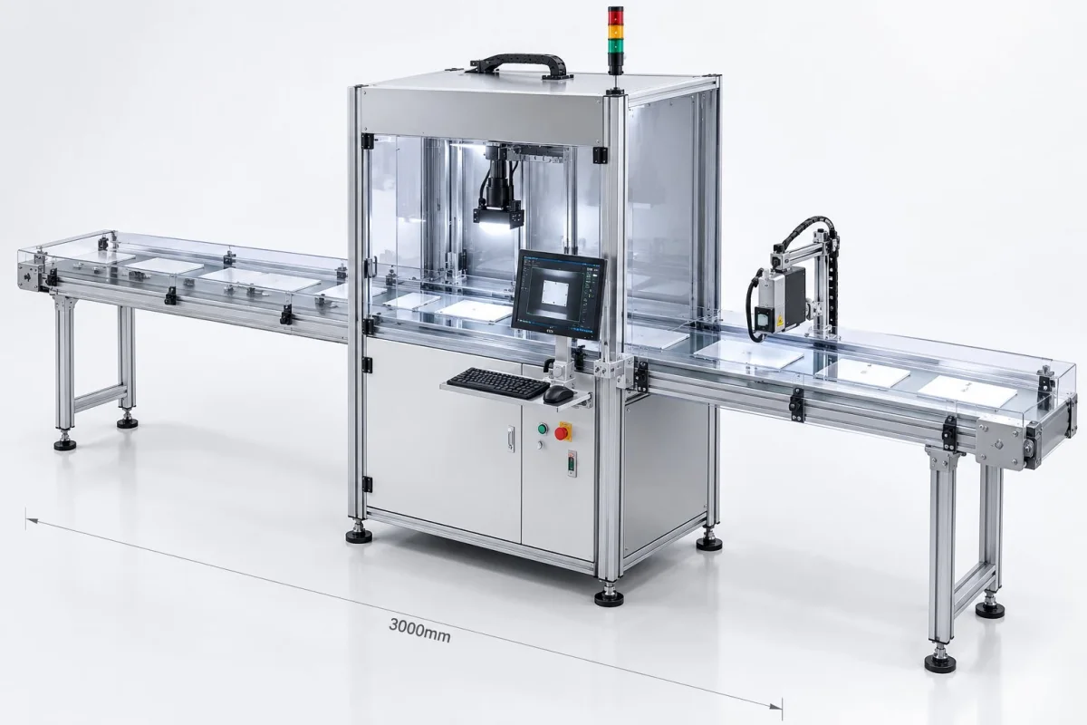
Pin presence/absence inspection: it judges whether pin headers and pins are complete, and whether they are deformed or skewed, and is suitable for connector assembly and PCB insertion process steps. The judgement usually does not assess details such as threads or dimensions, but judges Whether the visual feature at that position exists and matches expectations, output OK / NG and interlock with the production line.
Judges whether pin headers and pins are complete and whether they are deformed or tilted; suitable for connector assembly and PCB insertion processes.
The feasibility of "pin presence/absence inspection" depends on Whether the visual features of the object are stable and distinguishable, as well as the on-site optical and tooling conditions. Each item is expanded below in the order commonly used in inspection engineering.
Object Characteristics
How the object appears in the image
- Regularly arranged, large in number and closely spaced, suitable for whole-row verification
- Pins are slender and appear as thin-line structures in the image
- Abnormalities such as bending, tilting or missing parts may occur
- Metallic material with strong reflection, usually against a plastic base
inspection Challenges
Where Problems Really Occur on Site
- Pin spacing is small, so adjacent pins easily merge at low resolution
- Reflection at the pin tips creates bright spots that can mask the true form
- Bending and tilt require angle measurement, which demands higher resolution
- With many pins, the acceptance criteria must be consistent for every pin
Vision Judgement method
How acceptance criteria are set and why
The basic criterion is Whether an elongated target exists at each pin position, which can be done using axial projection of the pin body or region counting.
If deformation must be judged, the pin's Axial angle deviation or Needle tip position deviation, which requires higher imaging resolution and more stable datum positioning.
Applicable algorithm
Choose by the Form of the Acceptance Criteria, Not by Complexity
Projection / Counting
Project along the row direction to count pins and check position consistency
Geometric Measurement
Measure the pin angle or tip offset to judge deformation
Optical Precautions
Imaging conditions set the upper limit of feasibility
- Backlight or low-angle light makes thin pin contours clearer and reduces reflection interference
- For plastic base + metal pin combinations, polarization can reduce metal reflection
- Whole-row verification requires uniform illumination across the field of view, with the same acceptance criteria at the sides and in the middle
OK / NG Output
How results are judged and passed to the production line
| Inspection Status | judgement | Interlocking Action |
|---|---|---|
| All pins present, positions normal | OK | release |
| Missing Pin | NG | Block as missing part / defect |
| Obvious deformation or skewing | NG | Treat as a defect |
Applicable Industry
This type of inspection is common in the following industries
Common Question
The most common questions about this object
Can a Few Missing Pins Be Detected?
Yes, provided each needle can be resolved independently in the image. If the needle spacing is too small, resolution must be increased or imaging split by area; otherwise adjacent needles merge and the count becomes inaccurate.
Can bent pins be detected?
Yes, but it is a geometric measurement criterion and needs sufficient pixel resolution and a stable locating datum. We recommend providing known-skewed samples for validation to confirm the smallest detectable angle.
What are the acceptance criteria for this object?
The basic criterion is whether an elongated object exists at each pin position, which can be implemented by axial projection of the pin body or by regional counting.
What are the illumination requirements for this type of object?
Backlight or low-angle light makes fine pin contours clearer and reduces reflection interference. For a plastic base combined with metal pins, polarization can suppress metal reflections
What Are the Inspection Accuracy and Minimum Detectable Size?
It depends on the combination of field of view and camera resolution, and is affected by the lens, illumination and algorithm. To be added — the configuration must be derived from your minimum defect size, subject to the results of a measured sample trial.
How Do We Verify That Our Product Can Be Detected?
Please provide good pin header samples and samples with missing or bent pins, and state the pin spacing and minimum pin diameter.
Submit sample testing
Please provide good pin header samples and samples with missing or bent pins, and state the pin spacing and minimum pin diameter.
Submitted successfully
We have received your sample testing request. A solution engineer will contact you within 1 business day via contact you.
Need to assess imaging conditions, defect criteria and cycle time item by item? Go to the Full Requirement Assessment →
Send Us Your Workpiece and We Will Show You the Measured Results
Provide several OK and NG samples, and the solution engineer will run actual imaging and judgement tests on the equipment, then give inspection configuration recommendations that can be implemented, rather than just reading a specification table.