Motor Gasket Inspection
Motor gasket inspection: for hole diameter, contour, flatness and surface defects of flat motor gaskets, 8K line scan with programmable stripe light imaging is used, telecentric measurement for hole diameter and 3D laser line profiling for flatness, with a measured cycle time of 1.5–1.8 s/pcs.
Application Overview
Motor Gasket Hole Diameter, Contour and Flatness Measurement Solution
Inspection of motor gaskets (flat metal / composite gaskets) for hole diameter, contour, flatness and surface defects; 8K line-scan plus programmable stripe light imaging is used, with telecentric measurement of hole diameter and 3D line laser measurement of flatness.
The motor gasket is a flat sealing / positioning part in motor assembly; an out-of-tolerance hole diameter or flatness will directly cause oil leakage or assembly interference. It is a part where both dimensional and geometric tolerances matter, requiring a combination of dimensional measurement and 3D.
This station references the measured configuration of a motor gasket project: 8K monochrome line-scan camera + programmable stripe-light imaging, single-pixel accuracy about 0.018 mm/pixel, FOV 150 mm; hole diameter uses a telecentric lens + angle ring light for sub-pixel edge extraction; flatness is measured with a 3D line laser (repeatability about 0.013 mm), with a flatness requirement of about 0.02 mm.
Inspection is performed piece by piece, with a cycle time of about 1.5–1.8 s/pcs (the measured value for this project). The above are measured values from a motor gasket project and are subject to on-site commissioning; other gaskets must be recalibrated according to their drawings.
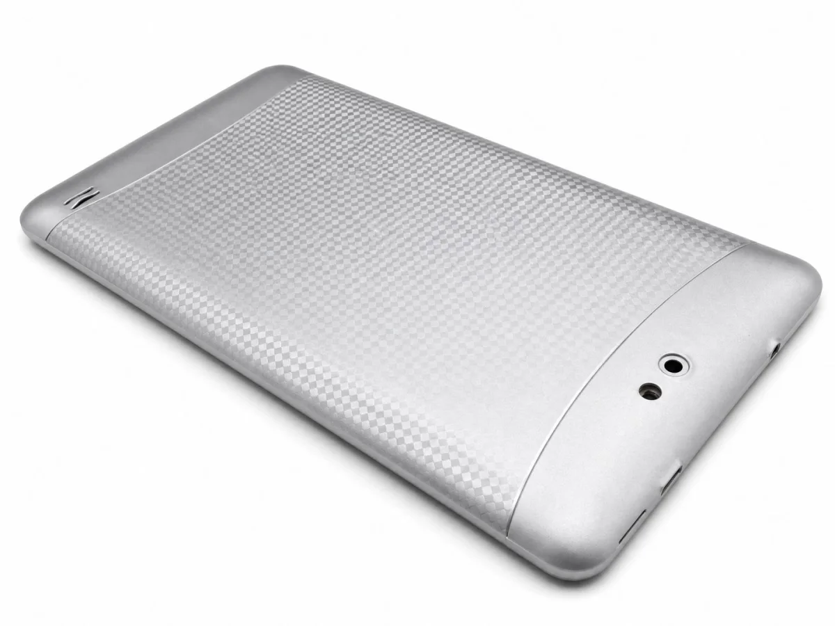
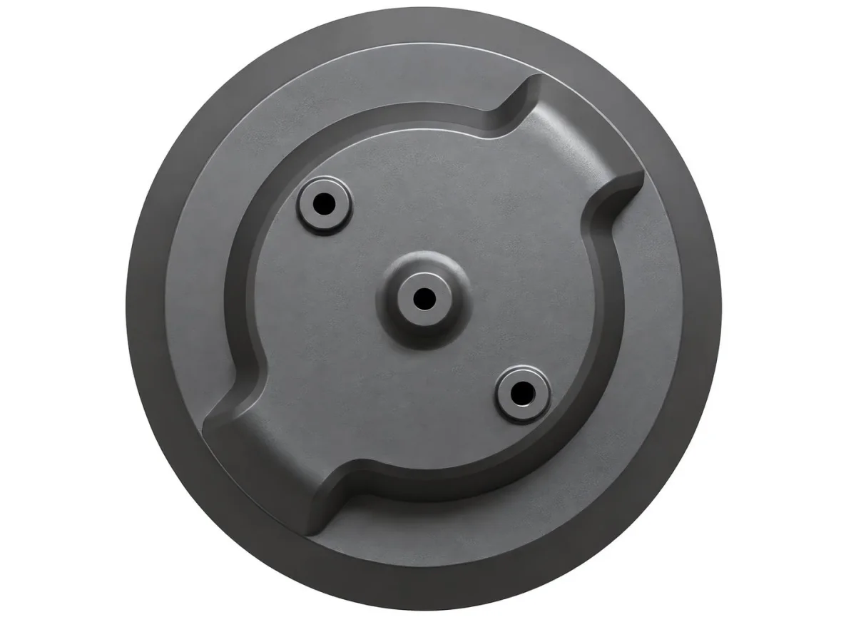
inspection Targets
What This Station Actually Has to Judge
| inspection item | Description |
|---|---|
| hole diameter | Hole diameters, position tolerance |
| contour | Outline contour out of tolerance |
| Flatness | Flatness geometric tolerance |
| Burr / Flash | Cutting Burr |
| scratch | Surface Scuff |
| stain | Oil Stains, Discoloration |
| short shot | Localized Short Shot |
Why Inspect
Problems with manual visual inspection at this step
Out-of-tolerance hole diameter and flatness on motor gaskets directly cause oil leakage or assembly interference; flatness cannot be seen with the naked eye but affects sealing, so dimension and 3D measurement must be combined for judgement.
Dimensional drift and burrs on gaskets in mass production require inline 100% inspection, which sampling cannot cover; dimensions and flatness must also be recorded to support process capability statistics.
- Hole flatness affects seal assembly
- Flatness cannot be seen by eye
- Batch drift requires full inline inspection
- Dimensions must be recorded for statistics
How Inspect
Stations and Inspection Chain
- 01 Gasket loading and positioning
- 02 8K line scan + programmable fringe light imaging
- 03 Telecentric lens + angled ring light measure hole diameter
- 04 Sub-pixel edge extraction
- 05 3D line laser surface scanning
- 06 Point cloud fitting for flatness
- 07 Contour and dimension comparison
- 08 OK/NG output
- 09 Image and data archiving
How to Inspect
For motor gaskets, 8K line-scan + programmable stripe-light imaging is used, hole diameter is measured at sub-pixel level with a telecentric lens + angle ring light, and flatness is fitted from 3D line laser scan point clouds — a combined imaging approach for dimensions + geometric tolerances (data from measurements on a motor gasket project; site conditions prevail).
inspection defect
| Defect Types | Typical Manifestations | Inspection Focus Points |
|---|---|---|
| Hole Diameter Out of Tolerance | Diameter / position offset | Telecentric + angled ring light |
| Flatness Out of Tolerance | Flatness Deviation Over 0.02 mm | 3D Laser Line Scanning |
| Burrs | Cutting Flash | Low-Angle Light |
| scratch | Abrasion | Program-controlled Fringe Light |
| stain | Oil Stains, Discoloration | Diffused Light |
| short shot | Localized Short Shot | Segmentation |
| Contour Anomaly | Outline Out of Tolerance | Contour Comparison |
Applicable equipment
Application Industry
Common Question
Why Does Motor Gasket Inspection Measure Both Dimensions and 3D?
Can it replace manual labor?
Is the accuracy data in this solution real?
How is flatness measured?
How accurate is hole diameter measurement?
What Is the Cycle Time?
Do I Need to Re-Tune When the Gasket Model Changes?
Submit sample testing
You can send typical OK/NG motor gaskets and drawings for measured testing: using a project configuration of 8K line scan + 3D line laser as a reference, the datum is recalibrated according to the drawing.
Submitted successfully
We have received your sample testing request. A solution engineer will contact you within 1 business day via contact you.
Need to assess imaging conditions, defect criteria and cycle time item by item? Go to the Full Requirement Assessment →
Can This Application Be Done? Sending a Sample for Testing Is the Most Direct Answer
Incoming material, part orientation and cycle time vary widely from factory to factory. Send us real samples and we will run imaging and judgement validation against your production line conditions, then give you a configuration proposal you can actually implement.