Electrical Equipment
For the assembly of distribution cabinets, control cabinets and electrical equipment, providing visual inspection solutions for component presence/absence, wiring correctness and marking verification.
Industry Production characteristics
How This Industry Produces Determines How Inspection Should Be Done
The visual inspection of electrical equipment revolves around two things: first, making the most common defects in this industry image clearly and consistently; second, connecting the judgement result reliably into the production line. Common implementation constraints in this industry are "wiring relationship criteria are complex and require model-based representation"; "the space inside the cabinet is long and narrow, making camera angles and lighting difficult to arrange". Whether detection can be stable depends on material optical properties, minimum defect size, and cycle time, and is subject to the results of a measured sample trial.
The characteristics of electrical equipment assembly are Wiring relationships are complex; a single mistake can cause a short circuit or failure. Traditionally this relies on manual checking against drawings and power-on testing, whereas visual inspection can find problems earlier during assembly.
The inspection challenge in this industry is not a single part, but "Which wire is connected to which terminal" — this kind of relational acceptance criterion, requiring a combination of position number recognition and logic verification.
Industry Inspection issues
Where problems actually occur on site
- Components missing or of the wrong model
- Miswiring and missed connections
- Terminal not crimped or not tightened
- Wire marker tube does not match the drawing
- Missing identification plate
Typical Inspection Objects
The Most Common Inspection Objects in This Industry
Typical Inspection Task
The judgments to be made on these objects
- Component presence/absence and model verification
- Wiring position verification (terminal designation recognition)
- Terminal crimping and locking check
- Wire marker tube content verification
- Identifier and nameplate verification
Vision Inspection Challenges
Implementation constraints specific to this industry
- Wiring relationship criteria are complex and need to be modeled
- Cabinet interiors are long and narrow, making camera angles and lighting layout difficult
- Wire harnesses block the view of some positions
- Characters on wire marker sleeves are small and dense
Choosing the right algorithm
Choose by Acceptance Criteria Form, Not by How Advanced It Is
OCR / Reference Designator Recognition
Recognize wire markers and terminal designations
Logic Verification
Compare the recognition result with the wiring table
Region presence
Component presence/absence judgement
acquisition and light source
Optical conditions set the upper limit of feasibility
- In-cabinet inspection requires compact light sources and cameras; watch the installation space
- For wire marker tube recognition, use uniform illumination so highlights do not affect the characters
- For deep cabinet interiors, use light guides or bar lights to illuminate in zones
OK / NG Judgement
How results are judged and used
| Inspection Status | judgement | Interlocking Action |
|---|---|---|
| Components and wiring all match the drawing | OK | Release to power-on test |
| Missing part / wrong connection present | NG | Intercept and indicate the specific point |
| Characters cannot be recognized | re-inspection | Escalate to manual checking |
PLC and Automation Interlocking
How results connect to the production line
Recommended output Specific points rather than an OK/NG verdict for the whole cabinet, so assembly workers can locate and repair directly.
When interlocked with MES, wiring verification records can be archived as factory quality evidence.
Applicable equipment
Common configuration forms for this type of inspection
Related Solutions
View the corresponding solution by inspection task
Common Question
The Questions Most Often Asked in This Industry
With Such Complex Wiring, Can Vision Inspect It?
Yes. The approach is to convert the wiring relationship into "position number recognition + logical comparison": recognize the number of each wire and the terminal position number it belongs to, then compare the result against the wiring table. The difficulty usually lies in the stability of recognizing the characters on the wire number sleeves.
Cabinet space is very small — how should the cameras be arranged?
It is recommended to confirm the available space and the viewing window at the solution stage. Several small cameras can be arranged by zone, or a movable inspection position can be used. Limited space is the most common constraint in projects of this kind.
For visual inspection in this industry, what needs to be solved first?
The implementation constraints commonly seen in this industry center on: "wiring relationship criteria are complex and need model-based representation"; "the space inside the cabinet is long and narrow, making viewing angles and lighting layout difficult"; "wire harnesses obscure some positions so they are not visible". These constraints affect both the imaging solution and the cycle-time design. Normally a sample trial is needed to validate before the configuration is finalized.
How does the inspection result interlock with the production line?
We recommend outputting specific points rather than a whole-cabinet OK/NG, so that assembly workers can locate rework directly. When interlocking with MES, wiring verification records can be archived as factory quality evidence.
What Equipment Configuration Does This Type of Inspection Generally Require?
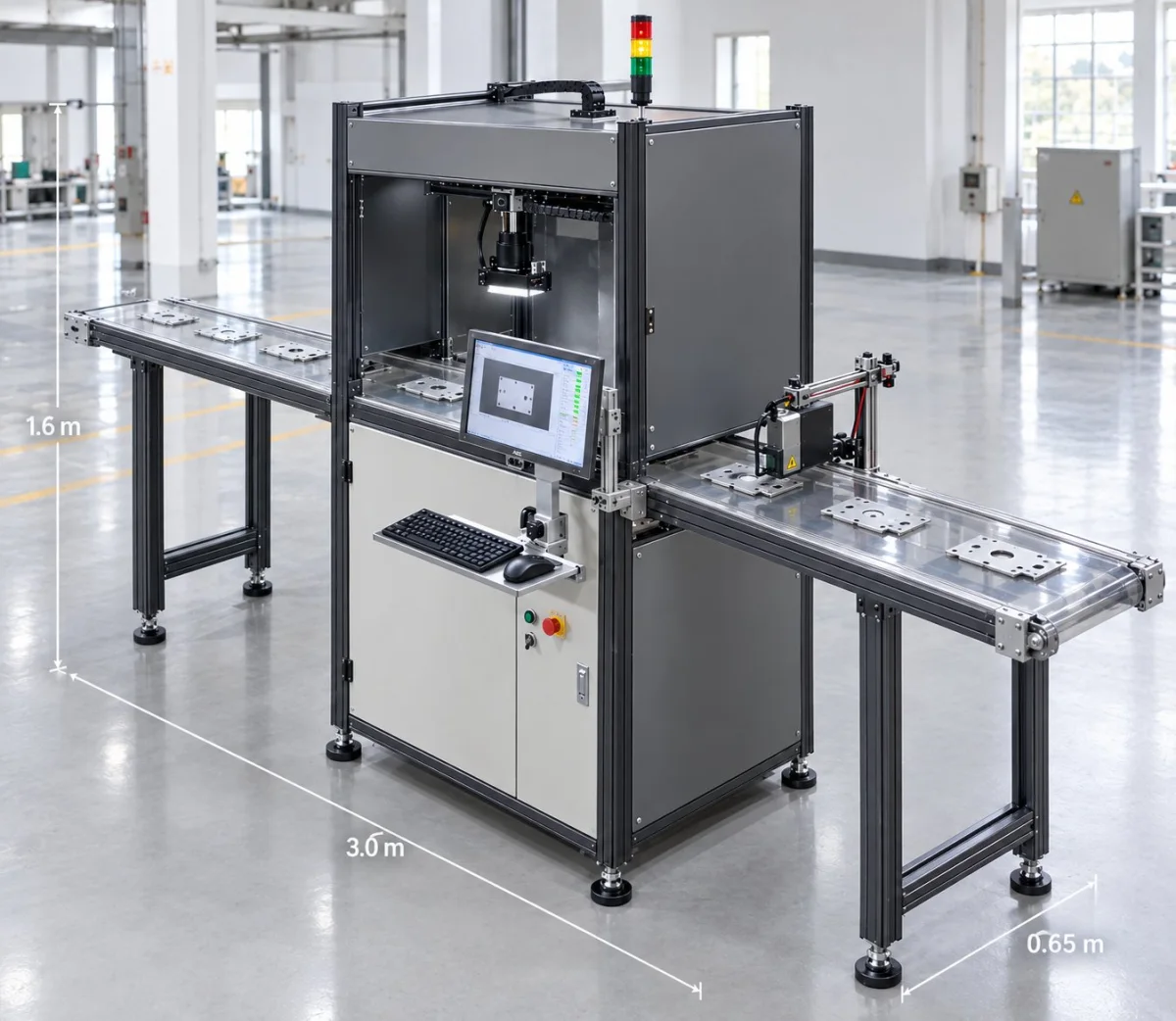
Common forms include: "EEK-SV5205C industrial vision presence/absence inspection equipment", "in-cabinet inspection station (compact configuration)", and "wiring verification system that works with MES". The specific machine model and quantity depend on the inspection area, minimum defect size, and line cycle time, and must be confirmed against the site conditions.
Which process steps in this industry benefit most from a visual inspection station?
The most common are: "component presence/absence and model verification"; "wiring position verification (reference designator recognition)"; "terminal crimping and locking inspection". Which process steps to actually instrument depends on the cost of defects escaping downstream and the cost of rework — the later a defect is found, the higher the cost.
How do we judge whether our product is suitable for visual inspection?
Please provide photos of the actual distribution cabinet / control cabinet and the wiring table, and state at which assembly step the verification is needed. In general, as long as the criteria can be stated clearly, defects can image clearly and consistently, and the cycle time matches the field of view, the project is feasible.
What inspection accuracy can be achieved?
Accuracy is not a fixed value that holds regardless of conditions. To be added — the minimum detectable size depends on the combination of field of view and camera resolution, and is also affected by illumination, lens and algorithm; the configuration must be derived from your minimum defect size and validated by measurement.
Submit sample testing
Please provide photos of the actual distribution cabinet / control cabinet and the wiring list, and state at which assembly step the verification is needed.
Submitted successfully
We have received your sample testing request. A solution engineer will contact you within 1 business day via contact you.
Need to assess imaging conditions, defect criteria and cycle time item by item? Go to the Full Requirement Assessment →
Inspection Configuration Based on Your Industry's Products and Cycle Time
Send us photos of the workpiece, the inspection requirement (what to inspect, and the tolerance for escapes and false calls), and the line cycle time, and our solution engineers will recommend the inspection method, optical solution, and interlocking configuration for that industry.