Motor
For motor manufacturing and assembly, providing visual inspection solutions for stator and rotor assembly, insulation parts, fasteners and appearance.
Industry Production characteristics
How This Industry Produces Determines How Inspection Should Be Done
The visual inspection of motors revolves around two things: first, making the most common defects in this industry image clearly and consistently; second, connecting the judgement result reliably into the production line. Common implementation constraints in this industry are "winding copper wire is highly reflective and complex in form"; "the laminated surface of silicon steel sheets has regular patterns that are easily confused with defects". Whether detection can be stable depends on material optical properties, minimum defect size, and cycle time, and is subject to the results of a measured sample trial.
Motor manufacturing is characterized by Dense windings, tight assembly tolerances, high operating vibration. A loose fastener or a single insulation break can develop into a failure during long-term operation.
Visual inspection in this industry often has to deal with "Complex structure + reflective surface" combination, the acceptance criteria design must rely more on geometric relationships than on color alone.
Industry Inspection issues
Where problems actually occur on site
- Insulating parts or slot wedges missing or misaligned
- Abnormal winding end form
- Missing or loose fasteners
- Rotor not fully seated
- Appearance dents and paint film defects
Typical Inspection Objects
The Most Common Inspection Objects in This Industry
Typical Inspection Task
The judgments to be made on these objects
- Checking for missing insulating parts and slot wedges
- End form inspection
- Fastener quantity and position verification
- Rotor fully seated confirmation
- Appearance anomaly identification
Vision Inspection Challenges
Implementation constraints specific to this industry
- Winding copper wire is highly reflective and complex in shape
- Laminated silicon steel sheets have regular surface patterns that are easily confused with defects
- Stator cavity is difficult to illuminate
- Frequent changeovers across multiple motor specifications
Choosing the right algorithm
Choose by Acceptance Criteria Form, Not by How Advanced It Is
Region presence
Presence/absence determination for insulating parts and slot wedges
Geometric Measurement
Correct assembly and position consistency
Anomaly Detection
Appearance and shape anomaly identification
acquisition and light source
Optical conditions set the upper limit of feasibility
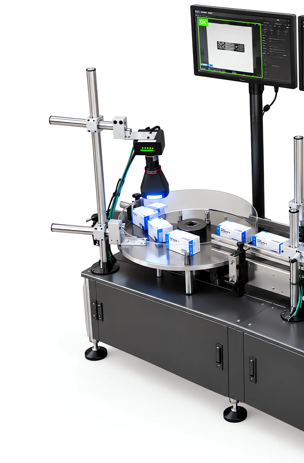
- For copper wire reflections, use diffuse + polarized light to reduce specular reflection
- For internal cavity inspection, use ring light guides or borescope-style illumination
- Keep the illumination configuration consistent when changing models frequently to reduce acceptance criteria drift
OK / NG Judgement
How results are judged and used
| Inspection Status | judgement | Interlocking Action |
|---|---|---|
| All assembly elements present, appearance normal | OK | release |
| Missing part / misalignment present | NG | Isolate and Rework |
| Appearance Anomaly | NG or re-inspection | Handle per process requirements |
PLC and Automation Interlocking
How results connect to the production line
We recommend interlocking with the winding and coil insertion equipment and feeding detected anomalies back to the upstream process step, so that tooling or equipment problems are found promptly.
When multiple specifications share a line, have the PLC send the model information to call up the recipe automatically.
Applicable equipment
Common configuration forms for this type of inspection
Related Solutions
View the corresponding solution by inspection task
Common Question
The Questions Most Often Asked in This Industry
Can winding end shapes be judged?
Yes, but the winding shape itself varies somewhat, so the acceptance criteria need tolerance design. We recommend collecting normal samples from several batches first, defining the range of "normal variation", and then setting the criteria for anomalies.
How should the stator cavity be illuminated?
A ring light guide or borescope-style light source is commonly used to illuminate inward from the cavity opening. The deeper and narrower the cavity, the harder the illumination, so we recommend testing the imaging result with actual workpieces during the solution stage.
For visual inspection in this industry, what needs to be solved first?
The implementation constraints commonly seen in this industry center on: "winding copper wire is highly reflective and complex in form"; "the stacked surface of silicon steel sheets has regular patterns that are easily confused with defects"; "the stator cavity is difficult to illuminate". These constraints affect both the imaging solution and the cycle-time design. Normally a sample trial is needed to validate before the configuration is finalized.
How does the inspection result interlock with the production line?
We recommend interlocking with the winding and coil insertion equipment, feeding detected abnormalities back to the upstream process step so that tooling or equipment problems are found in time. When multiple specifications share a line, we recommend having the PLC send the model information to call up the recipe automatically.
What Equipment Configuration Does This Type of Inspection Generally Require?
Common forms include: "EEK-SV5205C industrial vision presence/absence inspection equipment", "stator and rotor inspection station", "dedicated illumination unit for inner-cavity inspection". The specific machine model and quantity depend on the inspection area, the minimum defect size and the line cycle time, and must be confirmed according to the site conditions.
Which process steps in this industry benefit most from a visual inspection station?
The most common is: "screening for missing insulation parts and slot wedges"; "end-winding shape inspection"; "verification of fastener count and position". Which process steps to actually instrument depends on the cost of defects escaping downstream and the cost of rework — the later a defect is found, the higher the cost.
How do we judge whether our product is suitable for visual inspection?
Please provide physical stator and rotor parts and an assembled motor sample, and state at which process step verification is needed and how much space is available. In general, as long as the acceptance criteria can be stated clearly, the defects can image clearly and consistently, and the cycle time matches the field of view, the project's feasibility is confirmed.
What inspection accuracy can be achieved?
Accuracy is not a fixed value that holds regardless of conditions. To be added — the minimum detectable size depends on the combination of field of view and camera resolution, and is also affected by illumination, lens and algorithm; the configuration must be derived from your minimum defect size and validated by measurement.
Submit sample testing
Please provide the actual stator and rotor and an assembled motor sample, and state at which process step verification is needed and how much space is available.
Submitted successfully
We have received your sample testing request. A solution engineer will contact you within 1 business day via contact you.
Need to assess imaging conditions, defect criteria and cycle time item by item? Go to the Full Requirement Assessment →
Inspection Configuration Based on Your Industry's Products and Cycle Time
Send us photos of the workpiece, the inspection requirement (what to inspect, and the tolerance for escapes and false calls), and the line cycle time, and our solution engineers will recommend the inspection method, optical solution, and interlocking configuration for that industry.