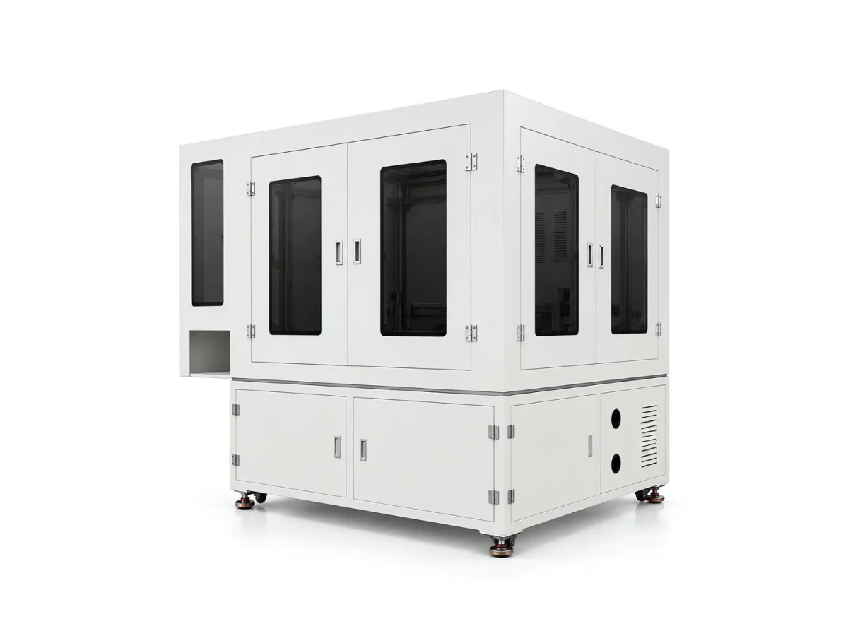
Die-Cut Tape AI Visual Inspection Equipment
Die-cut tape AI visual inspection equipment targets die-cut adhesive parts, performing inline inspection of out-of-tolerance dimensions, chipped corners, burrs, adhesive overflow, misalignment, short shot, foreign matter and other defects, with OK/NG output and production line interlocking.
Materials Overview
Transparent adhesive + adhesive overflow + die-cut burrs; dimensional accuracy is the key
The die-cut tape AI visual inspection equipment images die-cut adhesive parts; algorithms identify defects such as out-of-tolerance dimension, missing corner, burr, adhesive overflow, misalignment, short shot and foreign matter, output OK/NG results and interlock with the production line.
Die-cut tape is a part formed by punching adhesive material into a shape, commonly used for bonding and insulation in electronics, medical, and new energy applications. Its difficulty lies in "transparent adhesive + dimensions": tape is mostly transparent / translucent, so adhesive overflow and short shot have low contrast; and the dimensional accuracy of die-cut parts (shape, hole diameter, position) is often a key acceptance item.
Die-cut tape-specific defects include out-of-tolerance dimension (outline / hole diameter), missing corners, burrs (die-cutting flash), adhesive overflow (adhesive bleeding past the edge), misalignment (multi-layer offset), short shot and foreign matter. Dimensions and adhesive overflow are the key items.
Inspection uses a telecentric lens + sub-pixel edges for dimensional measurement and AI to judge excess adhesive and short shot; transparent parts require backlight or low-angle light. Changing the shape or the number of layers mainly requires adjusting the recipe.
Applicable Type
Single-sided die-cut tape
Focus on dimensions and adhesive overflow
Double-sided die-cut tape
Focus on misalignment and short shot
Multi-layer Die-cut Parts
Composite structure, the focus is on interlayer alignment
Die-Cut Rolls
Continuous strip waste removal, continuous inspection
Die-Cut Pieces
Single piece, inspected piece by piece with defect localization
Common defect
| Defect Types | Typical Manifestations | Inspection Focus Points |
|---|---|---|
| out-of-tolerance dimension | Outline / hole diameter mismatch | Telecentric + Sub-pixel |
| Missing corner | Incomplete Outline | Requires Positioned Measurement |
| Burr / Flash | Die-cut edge burr | Low-angle light forms a clear image |
| Excess adhesive | Adhesive Overflow at Edge | Transparent parts require backlight |
| Misalignment | Multi-Layer Offset | Requires Alignment Datum |
| short shot | Local Missing Material | Contrast Against Normal |
| foreign matter | Particles, Dust | Cleanliness Metric |
| wrinkle | Adhesive Face Bending | Low-Angle Light |
inspection Workflow
Complete chain from loading to judgment
- 01 Die-cut part loading / waste removal or single-piece infeed
- 02 Positioning and alignment datum
- 03 Triggered imaging (backlight + reflection)
- 04 Dimension and Contour Measurement
- 05 Excess adhesive / short shot segmentation
- 06 Defect classification and grading
- 07 Multi-layer alignment check
- 08 Synthesized OK / NG
- 09 Marking / rejection and image archiving
AI Inspection Principles
AI Visual Inspection Principles
Die-cut tape inspection is difficult because of "transparent adhesive + dimensions". The algorithm uses a telecentric lens and sub-pixel edges for dimensional measurement, and uses AI to judge adhesive overflow and short shot; transparent parts need backlight or low-angle light to improve contrast. Dimensional accuracy and adhesive overflow are key acceptance items.
For illumination, backlight / transmitted light is used for short shot and adhesive overflow in transparent adhesive; low-angle light is used for burrs and wrinkles; diffuse light is used for foreign matter and color difference. Telecentric lenses are used to suppress distortion in dimensional measurement.
For judgement, we recommend setting dimensions as high-precision measurement items and grading excess adhesive by area. Specific thresholds must be confirmed by measured testing of OK / NG samples.
Applicable Industry
Applicable equipment
Common Question
Can Adhesive Squeeze-Out on Clear Die-Cut Tape Be Captured?
Can Die-Cut Part Dimensions Be Measured Accurately?
Can Misalignment in Multilayer Die-Cut Parts Be Detected?
Can the Equipment Measure Tackiness?
What is the inspection accuracy?
What samples are needed to develop a solution?
Can It Be Integrated Into an Existing Production Line?
Submit sample testing
Send OK and NG samples of die-cut tape in different shapes and layer counts, along with your acceptance standards for dimensions and adhesive overflow; we will carry out dimensional measurement and measure the adhesive overflow, then give illumination plan recommendations.
Submitted successfully
We have received your sample testing request. A solution engineer will contact you within 1 business day via contact you.
Need to assess imaging conditions, defect criteria and cycle time item by item? Go to the Full Requirement Assessment →
Send Us Your Material and We Will Show You the Measured Results
Provide several OK and NG samples of the material, and a solution engineer will run actual imaging and judgement tests on the equipment to give a workable inspection configuration recommendation, rather than reading the datasheet alone.