Composite Material Inspection: Prepreg, Laminate and CFRP
Visual inspection of composite materials - prepreg, laminates, carbon fibre and glass fibre parts - for surface defects, fibre orientation and edge quality.
Solution Overview
Draw the boundary first: vision covers the surface and near-surface, while internal defects are left to non-destructive testing
The composite material AI visual inspection solution uses industrial cameras and application-specific lighting to inspect surface and near-surface defects in multilayer composite materials, including delamination, air bubbles, uneven coating, foreign matter and fiber misalignment; internal defects (delamination, internal porosity) must be handled by non-destructive methods such as ultrasound or X-ray.
When building an inspection solution for composite materials, the first thing is not choosing a camera, but Define the inspection boundary clearly. Composite material defects fall into two categories, surface defects and internal defects. Industrial vision can only handle the former; the latter require ultrasound, X-ray or infrared thermography.
Writing this boundary down clearly benefits both sides: the customer will not ask at acceptance "why was the delamination not detected", and the supplier will not be forced to promise something impossible.
At the surface and near-surface layer, the value of visual inspection is clear and verifiable: delamination and air bubbles appear as local changes in morphology or gloss, foreign matter appears as anomalies in grayscale and texture, and uneven coating appears as differences in reflection characteristics — all of which can be made to image clearly with a suitable illumination solution.
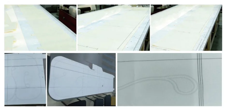
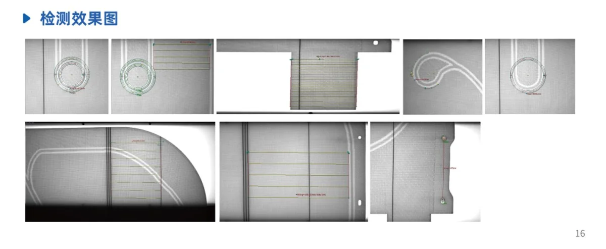
inspection Content
Judgement Items This Solution Addresses
| inspection item | Vision Feasibility | Description |
|---|---|---|
| Delamination / Bubbles | Detectable (requires dedicated lighting) | They appear as local shape or gloss anomalies, with low contrast under conventional illumination |
| Uneven coating / missing coating | Detectable | Differences in reflection characteristics require a stable illumination reference |
| Foreign Matter / Inclusion | Detectable | Varied morphologies, suitable for deep learning |
| Fiber misalignment / direction deviation | Detectable | Relies on clear fiber texture and texture direction analysis |
| Surface Crack | Detectable | Requires sufficient pixel equivalent |
| Scratch / Indentation | Detectable | Low-angle illumination forms a clearer image |
| Wrinkle / poor overlap | Detectable | Distinct surface morphology |
| Internal delamination / internal voids | Not visually detectable | Requires methods such as ultrasonic, X-ray, and infrared thermal imaging |
inspection Method
- 01 Material loading or lay-up
- 02 Leveling and fixing
- 03 Multi-angle / multi-mode imaging
- 04 Delamination and coating judgement
- 05 Foreign Matter Recognition
- 06 Fiber direction analysis
- 07 Surface defect judgement
- 08 Result Composition OK / NG
- 09 Marking and Records
Inspection Method Notes
The imaging solution for composite materials is usually "combined": it is hard for a single illumination to make delamination, coating and surface defects all form a clear image at the same time. Solution design therefore configures the matching illumination conditions for each type of target defect, and where necessary acquires images in several passes and then fuses them for judgement.
Judgement and interlocking
For composite materials, judgement goes beyond individual defects; more importantly, Defect Grading: delamination and coating defects are usually judged NG directly, foreign matter is graded by size and position, and surface scratches depend on depth and location.
The grading standard should not be set by the system on its own; a quantitative definition from your process and quality departments is required. What the system can do is execute the standard you give it consistently and record the judgement results and images completely.
- Delamination and coating defects are recommended to be judged NG directly
- Foreign matter handled by grade according to size and position
- Clearly distinguish two defect classes: "visually detectable" and "requiring non-destructive testing"
- Inspection images are archived by batch to support process traceability
Related Inspections Objects and Applications
Applicable Industry
Common Question
Can visual inspection detect internal delamination in composite materials?
Can delamination be seen in the image?
How Is Fiber Orientation Deviation Judged?
Composite surfaces are glossy. Will imaging be affected?
What is the inspection accuracy?
What Information Do You Need to Provide?
Submit sample testing
For composite material inspection, the boundaries must be drawn first. Please provide typical samples and your acceptance criteria; we will carry out a feasibility validation first, and then discuss the solution scope and acceptance criteria.
Submitted successfully
We have received your sample testing request. A solution engineer will contact you within 1 business day via contact you.
Need to assess imaging conditions, defect criteria and cycle time item by item? Go to the Full Requirement Assessment →
Submit Samples to Get a Visual Inspection Solution
Tell us the workpiece, inspection requirements, production line cycle time and your existing PLC / communication method, and our solution engineers will recommend the inspection method, optical configuration and interlocking solution.