Die-Cut Part Inspection with AI Visual Inspection
Inspection of die-cut parts for cutting completeness, dimension, burr and surface defects, at the speed of a die-cutting or converting line.
Solution Overview
The core of die-cut parts is "is the shape right, is there extra or missing material"
The die-cut parts AI visual inspection solution uses industrial cameras to image die-cut sheet products, inspecting outer contour, hole position accuracy, short shot and excess material, burrs, compression marks and foreign matter. It outputs OK/NG and interlocks with sorting, and is suitable for die-cut products such as foam, double-sided tape, conductive fabric, thermal pads and graphite sheets.
Die-cut parts have distinctive characteristics: Complex shape, small size, high volume. A die-cut part may have multiple hole positions, irregular contours, adhesive areas, and release film areas, and any position that is wrong makes the part nonconforming.
Inspection of this type of product has two focal points: first, Contour and Hole Position, which falls within dimensional measurement; the second is Short shot, excess material, burrs, crush marks, which falls within the scope of appearance and structural inspection. The former relies on sub-pixel edge extraction, the latter on defect inspection algorithms.
Die-cut parts are usually still attached to the carrier tape (roll material) or already singulated; the two forms require different inspection solutions: continuous imaging for carrier tape, piece-by-piece feeding for singulated parts.
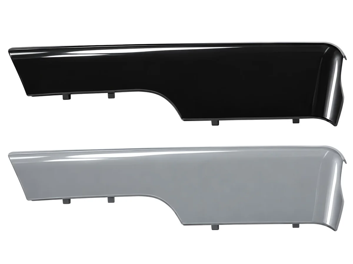
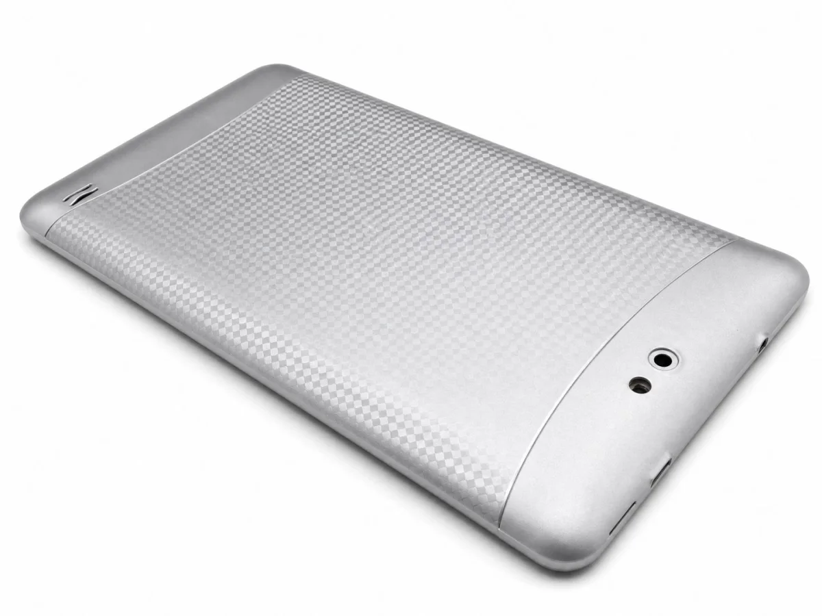
inspection Content
Judgement Items This Solution Addresses
| inspection item | Judgement Item | Remarks |
|---|---|---|
| Outline Contour | Outline dimensions, fillets, irregular contours | Sub-pixel edge + contour fitting |
| Hole Position and Spacing | Hole diameter, hole position coordinates, hole spacing | Requires a stable locating datum |
| Short Shot / Missing Parts | Local short shot, missing corner | Combined with contour and area statistics |
| Excess Material / Connected Parts | Excess material, uncut, still-connected material | Inspection of areas outside the contour |
| Burrs and Flash | Edge burrs, flash | Contour regularity analysis |
| Compression Marks and Scratches | Surface indentation, scratch | Low-angle Lighting |
| Foreign Matter and Dirt | Particles, glue marks, stains | Distinguished from material texture |
| Adhesive Area Inspection | Presence/absence of adhesive, coating coverage | Requires Dedicated Illumination |
inspection Method
- 01 Strip feeding or single-piece loading
- 02 Positioning and web guiding
- 03 Triggered Imaging
- 04 Contour and hole position measurement
- 05 Short shot and excess material judgement
- 06 Burr and surface defect judgement
- 07 Result Composition OK / NG
- 08 NG Marking or Rejection
- 09 Data Statistics
Inspection Method Notes
Judgement of die-cut parts is based on the "outer contour" as the datum: the actual contour is first extracted and then compared with the design contour to obtain dimensional and positional deviation; areas outside the contour are handled by the defect inspection algorithm. The stability of positioning therefore directly determines the credibility of the measurement results.
Judgement and interlocking
Judgement of die-cut parts often runs two logics in parallel, "dimension + appearance": dimensional items are judged by tolerance, while appearance items are judged by defect type and area. The thresholds for the two logics must be set separately and cannot be treated as one.
Also note: hole position and contour measurement of die-cut parts is very sensitive to the repeat positioning accuracy of the tooling. If the tooling's own repeat positioning accuracy is insufficient, the measurement results are meaningless.
- Separate thresholds for dimensional and appearance judgements
- Contour measurement accuracy is limited by the repeat positioning accuracy of the tooling, which must be confirmed as well
- Burr judgement is based mainly on contour regularity
- Special areas such as adhesive zones require dedicated illumination and judgement logic
Related Inspections Objects and Applications
Applicable Industry
Common Question
What Contour Measurement Accuracy Can Be Achieved on Die-Cut Parts?
With so many holes, can they all be measured in one pass?
How Do You Inspect Parts Still on the Carrier Strip?
To what extent can burrs be judged?
What if there are many die-cut part models and frequent changeovers?
What Information Do You Need to Provide?
Submit sample testing
Both dimensional and appearance judgement for die-cut parts require physical validation. Please provide drawings, tolerance requirements and samples containing defects, and we will carry out measurement and detection validation.
Submitted successfully
We have received your sample testing request. A solution engineer will contact you within 1 business day via contact you.
Need to assess imaging conditions, defect criteria and cycle time item by item? Go to the Full Requirement Assessment →
Submit Samples to Get a Visual Inspection Solution
Tell us the workpiece, inspection requirements, production line cycle time and your existing PLC / communication method, and our solution engineers will recommend the inspection method, optical configuration and interlocking solution.